содержание .. 611 612 613 614 ..
Nissan Tiida C11. Manual - part 613
EC-1102
< FUNCTION DIAGNOSIS >
[K9K]
COOLING FAN CONTROL
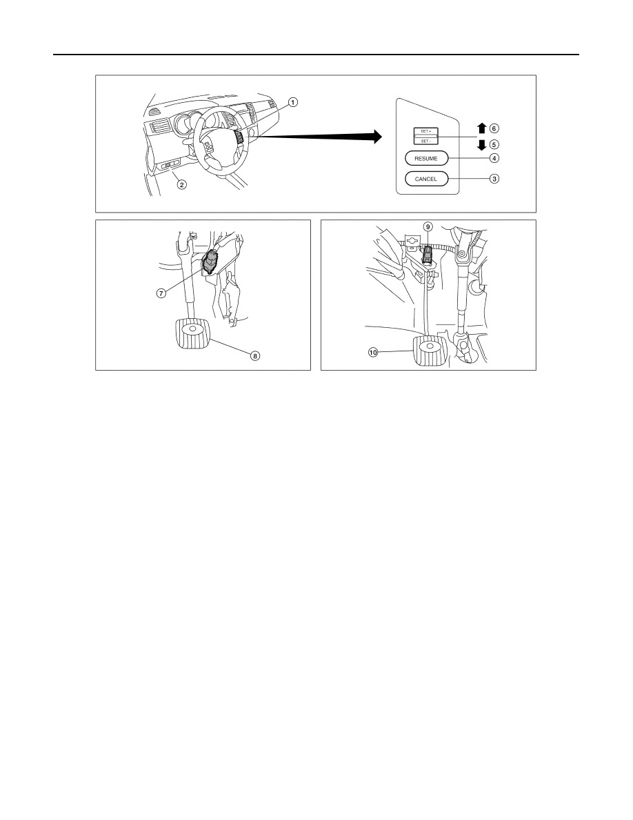
1.
ASCD steering switch
2.
ASCD switch
3.
CANCEL switch
4.
RESUME switch
5.
SET - switch
6.
SET + switch
7.
Stop lamp switch
8.
Brake pedal
9.
ASCD clutch switch
10. Clutch pedal
AWBIA0056ZZ