Nissan Tiida C11. Manual - part 492


  Главная      Nissan     Nissan Tiida C11 - Service Manual


поиск по сайту            


содержание   ..  490  491  492  493   ..


Nissan Tiida C11. Manual - part 492


EC-618

< COMPONENT DIAGNOSIS >

[HR16DE (WITHOUT EURO-OBD)]

HO2S2

Is the inspection result normal?

YES

>> GO TO 8.

NO

>> GO TO 7.

7.

REPLACE HEATED OXYGEN SENSOR 2

Replace heated oxygen sensor 2.

CAUTION:

• Discard any heated oxygen sensor which has been dropped from a height of more than 0.5 m (19.7

in) onto a hard surface such as a concrete floor; use a new one.

• Before installing new oxygen sensor, clean exhaust system threads using Oxygen Sensor Thread

Cleaner tool and approved anti-seize lubricant.

>> INSPECTION END

8.

CHECK INTERMITTENT INCIDENT

Refer to 

GI-55, "Intermittent Incident"

.

>> INSPECTION END

Component Inspection

INFOID:0000000001697502

1.

INSPECTION START

Do you have CONSULT-III?

Do you have CONSULT-III?

YES

>> GO TO 2.

NO

>> GO TO 3.

2.

CHECK HEATED OXYGEN SENSOR 2

With CONSULT-III

1.

Turn ignition switch ON and select “DATA MONITOR” mode with CONSULT-III.

2.

Start engine and warm it up to the normal operating temperature.

3.

Turn ignition switch OFF and wait at least 10 seconds.

4.

Start engine and keep the engine speed between 3,500 and 4,000 rpm for at least 1 minute under no load.

5.

Let engine idle for 1 minute.

6.

Select “FUEL INJECTION” in “ACTIVE TEST” mode, and select “HO2S2 (B1)” as the monitor item with
CONSULT-III.

7.

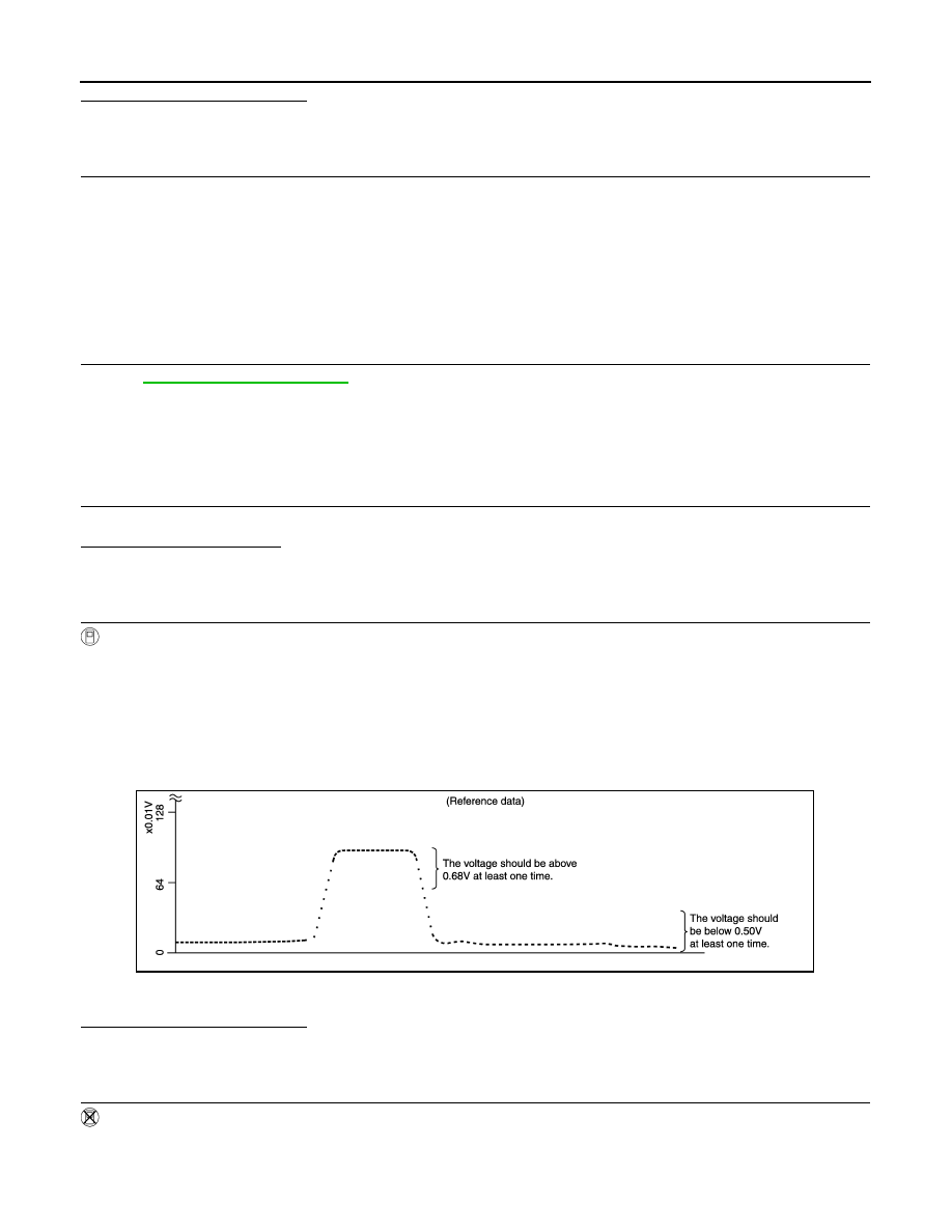
Check “HO2S2 (B1)” at idle speed when adjusting “FUEL INJECTION” to 

±

25%.

“HO2S2 (B1)” should be above 0.68V at least once when the “FUEL INJECTION” is +25%.
“HO2S2 (B1)” should be below 0.50V at least once when the “FUEL INJECTION” is 

25%.

Is the inspection result normal?

YES

>> INSPECTION END

NO

>> GO TO 6.

3.

CHECK HEATED OXYGEN SENSOR 2-I

Without CONSULT-III

1.

Start engine and warm it up to the normal operating temperature.

2.

Turn ignition switch OFF and wait at least 10 seconds.

3.

Start engine and keep the engine speed between 3,500 and 4,000 rpm for at least 1 minute under no load.

PBIB0551E

HO2S2

EC-619

< COMPONENT DIAGNOSIS >

[HR16DE (WITHOUT EURO-OBD)]

C

D

E

F

G

H

I

J

K

L

M

A

EC

N

P

O

4.

Let engine idle for 1 minute.

5.

Check the voltage between ECM harness connector and ground under the following condition.

Is the inspection result normal?

YES

>> INSPECTION END

NO

>> GO TO 4.

4.

CHECK HEATED OXYGEN SENSOR 2-II

Check the voltage between ECM harness connector and ground under the following condition.

Is the inspection result normal?

YES

>> INSPECTION END

NO

>> GO TO 5.

5.

CHECK HEATED OXYGEN SENSOR 2-III

Check the voltage between ECM harness connector and ground under the following condition.

Is the inspection result normal?

YES

>> INSPECTION END

NO

>> GO TO 6.

6.

REPLACE HEATED OXYGEN SENSOR 2

Replace heated oxygen sensor 2.

CAUTION:

• Discard any heated oxygen sensor which has been dropped from a height of more than 0.5 m (19.7

in) onto a hard surface such as a concrete floor; use a new one.

• Before installing new oxygen sensor, clean exhaust system threads using Oxygen Sensor Thread

Cleaner tool and approved anti-seize lubricant.

>> INSPECTION END

ECM

Ground

Condition

Voltage

Connector

Terminal

F8

50

(HO2S2 signal)

Ground

Revving up to 4,000 rpm under no load at 
least 10 times

The voltage should be above 0.68V at 
least once during this procedure.
The voltage should be below 0.50V at least 
once during this procedure.

ECM

Ground

Condition

Voltage

Connector

Terminal

F8

50

(HO2S2 signal)

Ground

Keeping engine speed at idle for 10 min-
utes

The voltage should be above 0.68V at 
least once during this procedure.
The voltage should be below 0.50V at least 
once during this procedure.

ECM

Ground

Condition

Voltage

Connector

Terminal

F8

50

(HO2S2 signal)

Ground

Coasting from 80 km/h (50 MPH) in 4th 
gear position

The voltage should be above 0.68V at 
least once during this procedure.
The voltage should be below 0.50V at least 
once during this procedure.

EC-620

< COMPONENT DIAGNOSIS >

[HR16DE (WITHOUT EURO-OBD)]

HO2S2 HEATER

HO2S2 HEATER

Description

INFOID:0000000001697503

SYSTEM DESCRIPTION

The ECM performs ON/OFF control of the heated oxygen sensor 2 heater corresponding to the engine speed,
amount of intake air and engine coolant temperature. 

OPERATION

Component Function Check

INFOID:0000000001697504

1.

CHECK HEATED OXYGEN SENSOR 2 HRATER FUNCTION

1.

Start engine and warm it up to the normal operating temperature.

2.

Turn ignition switch OFF and wait at least 10 seconds.

3.

Start engine and let it idle.

4.

Check the voltage between ECM harness connector and ground under the following condition.

: Average voltage for pulse signal (Actual pulse signal can be confirmed by oscilloscope.)

Is the inspection result normal?

YES

>> INSPECTION END

NO

>> Go to 

EC-620, "Diagnosis Procedure"

Diagnosis Procedure

INFOID:0000000001697505

1.

CHECK GROUND CONNECTION

1.

Turn ignition switch OFF.

2.

Check ground connection E21. Refer to Ground Inspection in 

GI-58, "Circuit Inspection"

.

Is the inspection result normal?

YES

>> GO TO 2.

Sensor

Input signal to ECM

ECM function

Actuator

Camshaft position sensor (PHASE)
Crankshaft position sensor (POS)

Engine speed

Heated oxygen sensor 2 
heater control

Heated oxygen sensor 2 heater

Engine coolant temperature sensor

Engine coolant temperature

Mass air flow sensor

Amount of intake air

Engine speed rpm

Heated oxygen sensor 2 heater

Above 3,900

OFF

Below 3,900 rpm after the following conditions are met.
• Engine: After warming up
• Keeping the engine speed between 3,500 and 4,000 rpm for 1 

minute and at idle for 1 minute under no load

ON

ECM

Ground

Condition

Voltage signal

Connector

Terminal

F7

5

(HO2S2 heater signal)

Ground

At idle

Approx. 10V

Engine speed: Above 3,900 rpm

BATTERY VOLTAGE

(11 - 14V)

JMBIA0325GB

HO2S2 HEATER

EC-621

< COMPONENT DIAGNOSIS >

[HR16DE (WITHOUT EURO-OBD)]

C

D

E

F

G

H

I

J

K

L

M

A

EC

N

P

O

NO

>> Repair or replace ground connection.

2.

CHECK HO2S2 POWER SUPPLY CIRCUIT

1.

Disconnect HO2S2 harness connector.

2.

Turn ignition switch ON.

3.

Check the voltage between HO2S2 harness connector and ground.

Is the inspection result normal?

YES

>> GO TO 4.

NO

>> GO TO 3.

3.

DETECT MALFUNCTIONING PART

Check the following.
• IPDM E/R connector E11
• 10A fuse (No. 56)
• Harness for open or short between heated oxygen sensor 2 and fuse

>> Repair open circuit or short to ground or short to power in harness or connectors.

4.

CHECK HO2S2 OUTPUT SIGNAL CIRCUIT FOR OPEN AND SHORT

1.

Turn ignition switch OFF.

2.

Disconnect ECM harness connector.

3.

Check the continuity between HO2S2 harness connector and ECM harness connector.

4.

Also check harness for short to ground and short to power.

Is the inspection result normal?

YES

>> GO TO 6.

NO

>> GO TO 5.

5.

DETECT MALFUNCTIONING PART

Check the following.
• Harness connectors F121, E7
• Harness for open or short between heated oxygen sensor 2 and ECM

>> Repair open circuit or short to ground or short to power in harness or connectors.

6.

CHECK HO2S2 HEATER

Refer to 

EC-622, "Component Inspection"

.

Is the inspection result normal?

YES

>> GO TO 8.

NO

>> GO TO 7.

7.

REPLACE HEATED OXYGEN SENSOR 2

Replace heated oxygen sensor 2.

CAUTION:

• Discard any heated oxygen sensor which has been dropped from a height of more than 0.5 m (19.7

in) onto a hard surface such as a concrete floor; use a new one.

• Before installing new oxygen sensor, clean exhaust system threads using Oxygen Sensor Thread

Cleaner tool and approved anti-seize lubricant.

HO2S2

Ground

Voltage

Connector

Terminal

E58

2

Ground

Battery voltage

HO2S2

ECM

Continuity

Connector

Terminal

Connector

Terminal

E58

3

F7

5

Existed


содержание   ..  490  491  492  493   ..