Nissan Tiida C11. Manual - part 373


  Главная      Nissan     Nissan Tiida C11 - Service Manual


поиск по сайту            


содержание   ..  371  372  373  374   ..


Nissan Tiida C11. Manual - part 373


EC-142

< COMPONENT DIAGNOSIS >

[HR16DE (WITH EURO-OBD)]

P0117, P0118 ECT SENSOR

P0117, P0118 ECT SENSOR

Description

INFOID:0000000001670907

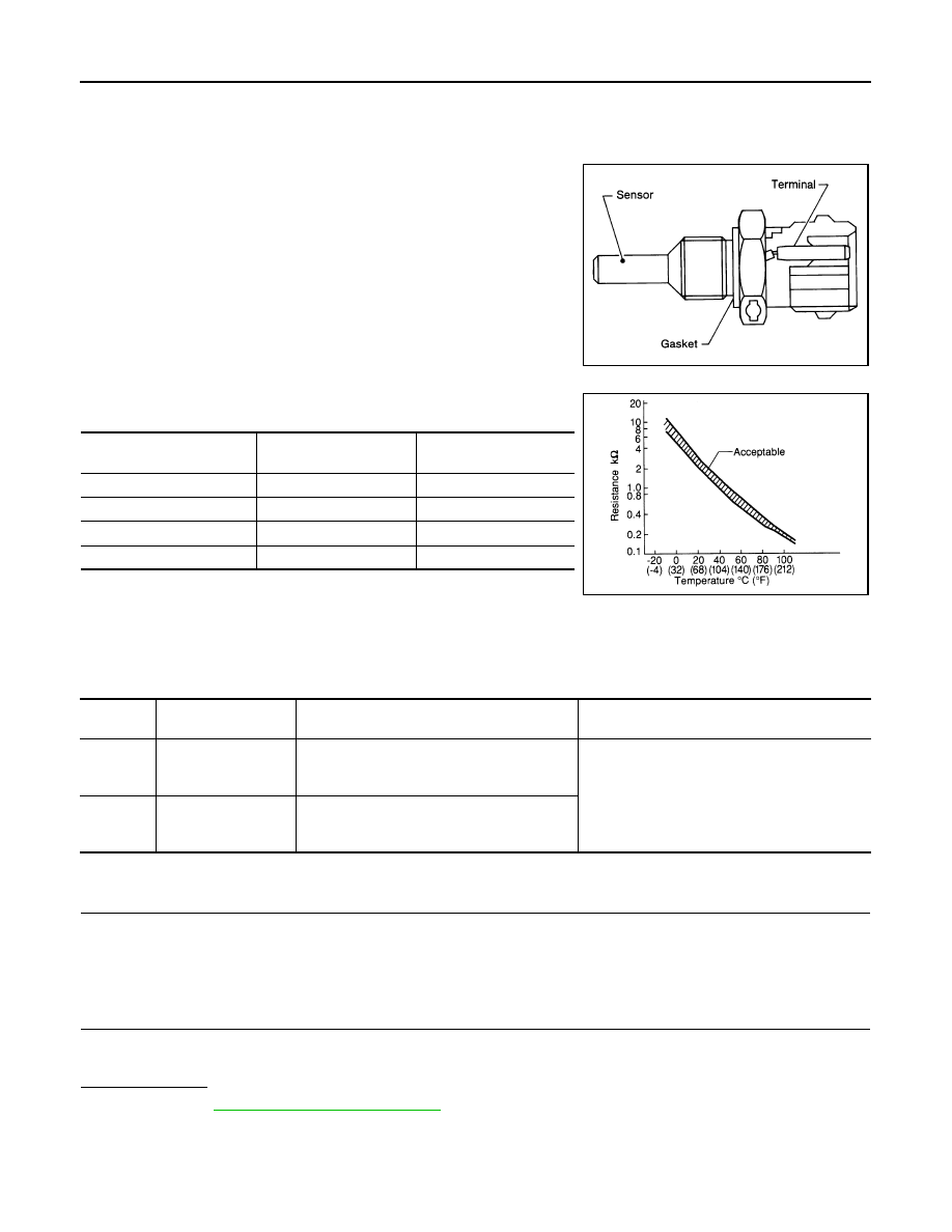
The engine coolant temperature sensor is used to detect the engine
coolant temperature. The sensor modifies a voltage signal from the
ECM. The modified signal returns to the ECM as the engine coolant
temperature input. The sensor uses a thermistor which is sensitive to
the change in temperature. The electrical resistance of the ther-
mistor decreases as temperature increases.

<Reference data>

*: These data are reference values and are measured between ECM terminal 38
(Engine coolant temperature sensor) and 44.

DTC Logic

INFOID:0000000001670908

DTC DETECTION LOGIC

DTC CONFIRMATION PROCEDURE

1.

PRECONDITIONING

If DTC Confirmation Procedure has been previously conducted, always turn ignition switch OFF and wait at
least 10 seconds before conducting the next test.

>> GO TO 2.

2.

PERFORM DTC CONFIRMATION PROCEDURE

1.

Turn ignition switch ON and wait at least 5 seconds.

2.

Check DTC.

Is DTC detected?

YES

>> Go to 

EC-143, "Diagnosis Procedure"

.

NO

>> INSPECTION END

SEF594K

Engine coolant temperature

°

C (

°

F)

Voltage*

V

Resistance

k

–10 (14)

4.4

7.0 - 11.4

20 (68)

3.5

2.1 - 2.9

50 (122)

2.2

0.68 - 1.00

90 (194)

0.9

0.236 - 0.260

SEF012P

DTC No.

Trouble Diagnosis 

Name

DTC Detecting Condition

Possible Cause

P0117

Engine coolant tem-
perature sensor cir-
cuit low input

An excessively low voltage from the sensor is 
sent to ECM.

• Harness or connectors

(The sensor circuit is open or shorted.)

• Engine coolant temperature sensor 

P0118

Engine coolant tem-
perature sensor cir-
cuit high input

An excessively high voltage from the sensor is 
sent to ECM.

P0117, P0118 ECT SENSOR

EC-143

< COMPONENT DIAGNOSIS >

[HR16DE (WITH EURO-OBD)]

C

D

E

F

G

H

I

J

K

L

M

A

EC

N

P

O

Diagnosis Procedure

INFOID:0000000001670909

1.

CHECK GROUND CONNECTION

1.

Turn ignition switch OFF.

2.

Check ground connection E15. Refer to Ground Inspection in 

GI-58, "Circuit Inspection"

.

Is the inspection result normal?

YES

>> GO TO 2.

NO

>> Repair or replace ground connection.

2.

CHECK ECT SENSOR POWER SUPPLY CIRCUIT

1.

Disconnect engine coolant temperature (ECT) sensor harness connector.

2.

Turn ignition switch ON.

3.

Check the voltage between ECT sensor harness connector and ground.

Is the inspection result normal?

YES

>> GO TO 3.

NO

>> Repair open circuit or short to ground or short to power in harness or connectors.

3.

CHECK ECT SENSOR GROUND CIRCUIT FOR OPEN AND SHORT

1.

Turn ignition switch OFF.

2.

Disconnect ECM harness connector.

3.

Check the continuity between ECT sensor harness connector and ECM harness connector.

4.

Also check harness for short to ground and short to power.

Is the inspection result normal?

YES

>> GO TO 4.

NO

>> Repair open circuit or short to ground or short to power in harness or connectors.

4.

CHECK ENGINE COOLANT TEMPERATURE SENSOR

Refer to 

EC-143, "Component Inspection"

.

Is the inspection result normal?

YES

>> GO TO 5.

NO

>> Replace engine coolant temperature sensor.

5.

CHECK INTERMITTENT INCIDENT

Refer to 

GI-55, "Intermittent Incident"

.

>> INSPECTION END

Component Inspection

INFOID:0000000001670910

1.

CHECK ENGINE COOLANT TEMPERATURE SENSOR

1.

Turn ignition switch OFF.

2.

Disconnect engine coolant temperature sensor harness connector.

3.

Remove engine coolant temperature sensor.

ECT sensor

Ground

Voltage

Connector

Terminal

F6

1

Ground

Approx. 5V

ECT sensor

ECM

Continuity

Connector

Terminal

Connector

Terminal

F6

2

F11

44

Existed

EC-144

< COMPONENT DIAGNOSIS >

[HR16DE (WITH EURO-OBD)]

P0117, P0118 ECT SENSOR

4.

Check resistance between engine coolant temperature sensor
terminals by heating with hot water as shown in the figure.

Is the inspection result normal?

YES

>> INSPECTION END

NO

>> Replace engine coolant temperature sensor.

Terminals

Condition

Resistance

1 and 2

Temperature

°

C (

°

F)

20 (68)

2.1 - 2.9 k

50 (122)

0.68 - 1.00 k

90 (194)

0.236 - 0.260 k

JMBIA0080ZZ

P0122, P0123 TP SENSOR

EC-145

< COMPONENT DIAGNOSIS >

[HR16DE (WITH EURO-OBD)]

C

D

E

F

G

H

I

J

K

L

M

A

EC

N

P

O

P0122, P0123 TP SENSOR

Description

INFOID:0000000001670911

Electric throttle control actuator consists of throttle control motor,
throttle position sensor, etc. The throttle position sensor responds to
the throttle valve movement. 
The throttle position sensor has two sensors. These sensors are a
kind of potentiometers which transform the throttle valve position into
output voltage, and emit the voltage signal to the ECM. In addition,
these sensors detect the opening and closing speed of the throttle
valve and feed the voltage signals to the ECM. The ECM judges the
current opening angle of the throttle valve from these signals and the
ECM controls the throttle control motor to make the throttle valve
opening angle properly in response to driving condition.

DTC Logic

INFOID:0000000001670912

DTC DETECTION LOGIC

NOTE:
If DTC P0122 or P0123 is displayed with DTC P1229, first perform the trouble diagnosis for DTC P1229.
Refer to 

EC-265, "DTC Logic"

.

DTC CONFIRMATION PROCEDURE

1.

PRECONDITIONING

If DTC Confirmation Procedure has been previously conducted, always turn ignition switch OFF and wait at
least 10 seconds before conducting the next test.
TESTING CONDITION:
Before performing the following procedure, confirm that battery voltage is more than 10V at idle.

>> GO TO 2.

2.

PERFORM DTC CONFIRMATION PROCEDURE

1.

Start engine and let it idle for 1 second.

2.

Check DTC.

Is DTC detected?

YES

>> Go to 

EC-145, "Diagnosis Procedure"

.

NO

>> INSPECTION END

Diagnosis Procedure

INFOID:0000000001670913

1.

CHECK GROUND CONNECTION

1.

Turn ignition switch OFF.

2.

Check ground connection E15. Refer to Ground Inspection in 

GI-58, "Circuit Inspection"

.

Is the inspection result normal?

YES

>> GO TO 2.

NO

>> Repair or replace ground connection.

2.

CHECK THROTTLE POSITION SENSOR 2 POWER SUPPLY CIRCUIT

1.

Disconnect electric throttle control actuator harness connector.

2.

Turn ignition switch ON.

PBIB0145E

DTC No.

Trouble diagnosis name

DTC detecting condition

Possible cause

P0122

Throttle position sensor 
2 circuit low input

An excessively low voltage from the TP sensor 
2 is sent to ECM.

• Harness or connectors

(TP sensor 2 circuit is open or shorted.)

• Electric throttle control actuator

(TP sensor 2)

P0123

Throttle position sensor 
2 circuit high input

An excessively high voltage from the TP sensor 
2 is sent to ECM.


содержание   ..  371  372  373  374   ..