Nissan Tiida C11. Manual - part 352


  Главная      Nissan     Nissan Tiida C11 - Service Manual


поиск по сайту            


содержание   ..  350  351  352  353   ..


Nissan Tiida C11. Manual - part 352


EC-58

< FUNCTION DIAGNOSIS >

[HR16DE (WITH EURO-OBD)]

AIR CONDITIONING CUT CONTROL

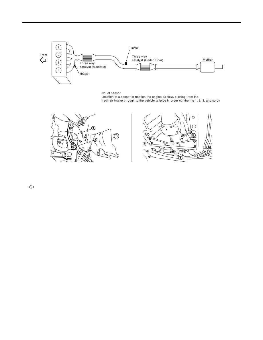
1.

Exhaust manifold

2.

Heated oxygen sensor 1

3.

Heated oxygen sensor 2

4.

Heated oxygen sensor 2 harness 
connector

Vehicle front

PBIB2942E

PBIB2943E

AIR CONDITIONING CUT CONTROL

EC-59

< FUNCTION DIAGNOSIS >

[HR16DE (WITH EURO-OBD)]

C

D

E

F

G

H

I

J

K

L

M

A

EC

N

P

O

1.

Cooling fan motor harness connec-
tor

2.

Crankshaft position sensor

3.

Stop lamp switch

4.

Brake pedal

5.

Accelerator pedal position sensor 
harness connector

6.

Accelerator pedal position sensor

7.

Accelerator pedal

8.

Fuel level sensor unit and fuel pump 
harness connector (view with in-
spection hole cover removed)

9.

Fuel pressure regulator

10. Fuel pump

AWBIA0044ZZ

EC-60

< FUNCTION DIAGNOSIS >

[HR16DE (WITH EURO-OBD)]

AIR CONDITIONING CUT CONTROL

Component Description

INFOID:0000000001161153

1.

ASCD steering switch

2.

MAIN switch

3.

CANCEL switch

4.

SET/COAST switch

5.

RESUME/ACCELERATE switch

6.

ASCD brake switch

7.

Stop lamp switch

8.

ASCD clutch switch

9.

Clutch pedal

ALBIA0273ZZ

Component

Reference

Accelerator pedal position sensor

EC-286, "Description"

Camshaft position sensor (PHASE)

EC-201, "Description"

Crankshaft position sensor (POS)

EC-197, "Description"

Engine coolant temperature sensor

EC-142, "Description"

Refrigerant pressure sensor

EC-326, "Description"

Vehicle speed sensor

EC-213, "Description"

AUTOMATIC SPEED CONTROL DEVICE (ASCD)

EC-61

< FUNCTION DIAGNOSIS >

[HR16DE (WITH EURO-OBD)]

C

D

E

F

G

H

I

J

K

L

M

A

EC

N

P

O

AUTOMATIC SPEED CONTROL DEVICE (ASCD)

System Diagram

INFOID:0000000001161154

System Description

INFOID:0000000001161155

INPUT/OUTPUT SIGNAL CHART

*: This signal is sent to the ECM through CAN communication line

BASIC ASCD SYSTEM

Refer to Owner's Manual for ASCD operating instructions.
Automatic Speed Control Device (ASCD) allows a driver to keep vehicle at predetermined constant speed
without depressing accelerator pedal. Driver can set vehicle speed in advance between approximately 40 km/
h (25 MPH) and 153 km/h (95 MPH).
ECM controls throttle angle of electric throttle control actuator to regulate engine speed.
Operation status of ASCD is indicated by CRUISE lamp and SET lamp in combination meter. If any malfunc-
tion occurs in ASCD system, it automatically deactivates control.
NOTE:
Always drive vehicle in safe manner according to traffic conditions and obey all traffic laws.

SET OPERATION

Press MAIN switch. (The CRUISE lamp in combination meter illuminates.)
When vehicle speed reaches a desired speed between approximately 40 km/h (25 MPH) and 153 km/h (95
MPH), press SET/COAST switch. (Then SET lamp in combination meter illuminates.)

ACCELERATE OPERATION

If the RESUME/ACCELERATE switch is pressed during cruise control driving, increase the vehicle speed until
the switch is released or vehicle speed reaches maximum speed controlled by the system.
And then ASCD will keep the new set speed.

CANCEL OPERATION

JMBIA0823GB

Sensor

Input signal to ECM

ECM function

Actuator

ASCD brake switch

Brake pedal operation

ASCD vehicle speed control

Electric throttle control 
actuator

Stop lamp switch

ASCD clutch switch (M/T models)

Clutch pedal operation

ASCD steering switch

ASCD steering switch operation

Park/neutral position switch

Gear position

Combination meter

Vehicle speed*

TCM (A/T models)

Powertrain revolution*


содержание   ..  350  351  352  353   ..