Nissan Tiida C11. Manual - part 336


  Главная      Nissan     Nissan Tiida C11 - Service Manual


поиск по сайту            


содержание   ..  334  335  336  337   ..


Nissan Tiida C11. Manual - part 336


DLK-754

< REMOVAL AND INSTALLATION >

[WITHOUT I-KEY, WITH SUPER LOCK]

REAR DOOR LOCK

REAR DOOR LOCK

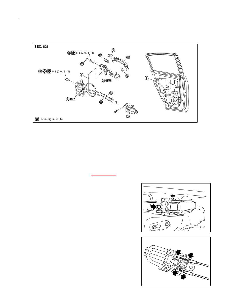
Component Parts Location

INFOID:0000000001732064

Removal and Installation

INFOID:0000000001732065

REMOVAL

1.

Remove the partition glass. Refer to 

XX-XX, "*****"

.

2.

Support door glass while lifting it up to the door window completely closed position.

3.

Remove inside handle bolt, slide handle toward rear of vehicle,
disconnect it from the door panel, and remove the inside handle.

4.

Disconnect the inside handle and lock knob cables from the
inside handle.

CAUTION:

During removal and installation, do not to bend the ends of
the lock knob cable and inside handle cable.

1.

Rear door

2.

Inside handle

3.

Inside handle cable

4.

Door lock assembly

5.

TORX bolt (T30)

6.

Outside handle cable

7.

Grommet

8.

TORX bolt (T30)

9.

Rear gasket

10. Outside handle escutcheon

11. Outside handle

12. Front gasket

13. Lock knob cable

14. Outside handle bracket

PIIB6530E

PIIB6524E

PIIB6525E

REAR DOOR LOCK

DLK-755

< REMOVAL AND INSTALLATION >

[WITHOUT I-KEY, WITH SUPER LOCK]

C

D

E

F

G

H

I

J

L

M

A

B

DLK

N

O

P

5.

Remove the door side grommet, and the outside handle
escutcheon screw. 

6.

Pull the outside handle forward (1), while removing outside han-
dle escutcheon (2).

7.

Pull outside door handle forward (1), and slide it toward the rear
of the vehicle to remove (2).

8.

Remove the front and rear gaskets.

9.

Remove the door lock assembly screws.

PIIB5808E

PIIB5809E

PIIB5810E

PIIB6526E

 : 5.8 N·m (0.6 kg-m, 51.4 in-lb)

PIIB6527E

DLK-756

< REMOVAL AND INSTALLATION >

[WITHOUT I-KEY, WITH SUPER LOCK]

REAR DOOR LOCK

10. Slide the outside handle bracket toward the rear of vehicle,

remove the outside handle bracket and the door lock assembly.

11. If equipped, disconnect the door lock assembly electrical connector.
12. Disconnect the outside handle cable from the outside handle

bracket.

INSTALLATION

Installation is in the reverse order of removal.

CAUTION:

• To install each rod, be sure to rotate the rod holder until a click is felt.
• When installing door lock assembly, be careful when rotating the outside handle cable as shown. 
- Place the outside handle bracket cable on the inside of door

lock assembly before installing.

PIIB6528E

PIIB5815E

PIIB6529E

BACK DOOR LOCK

DLK-757

< REMOVAL AND INSTALLATION >

[WITHOUT I-KEY, WITH SUPER LOCK]

C

D

E

F

G

H

I

J

L

M

A

B

DLK

N

O

P

BACK DOOR LOCK

Removal and Installation

INFOID:0000000001732066

BACK DOOR LOCK

Removal

1.

Remove the back door finisher lower. Refer to 

XX-XX, "*****"

.

2.

Remove the bolts, disconnect the electrical connector and sepa-
rate the lock from the door. 

Installation

Installation is in the reverse order of removal.

BACK DOOR HANDLE

Removal

1.

Remove the back door finisher lower. Refer to 

XX-XX, "*****"

.

2.

Disconnect the harness connectors (1), remove the nuts and the
back door handle (A).

3.

Release the clips and remove the switch from the housing.

Installation

Installation is in the reverse order of removal.

LIIA2607E

LIIA2669E

LIIA2609E


содержание   ..  334  335  336  337   ..