содержание .. 1434 1435 1436 1437 ..
Nissan Tiida C11. Manual - part 1436
WCS-26
< COMPONENT DIAGNOSIS >
KEY SWITCH SIGNAL CIRCUIT (WITH INTELLIGENT KEY)
KEY SWITCH SIGNAL CIRCUIT (WITH INTELLIGENT KEY)
Description
INFOID:0000000001722936
Transmits a key switch signal to the BCM.
Component Function Check
INFOID:0000000001722937
1.
CHECK BCM INPUT SIGNAL
Select “DATA MONITOR” for “BCM” and check the “KEY IN SW” monitor value.
>> Inspection End.
Diagnosis Procedure
INFOID:0000000001722938
1.
CHECK FUSE
Check if the key switch and ignition knob switch 10A fuse (No. 31, located in the fuse and relay box) is blown.
Is the fuse blown?
YES
>> Be sure to repair the cause of malfunction before installing new fuse.
NO
>> GO TO 2
2.
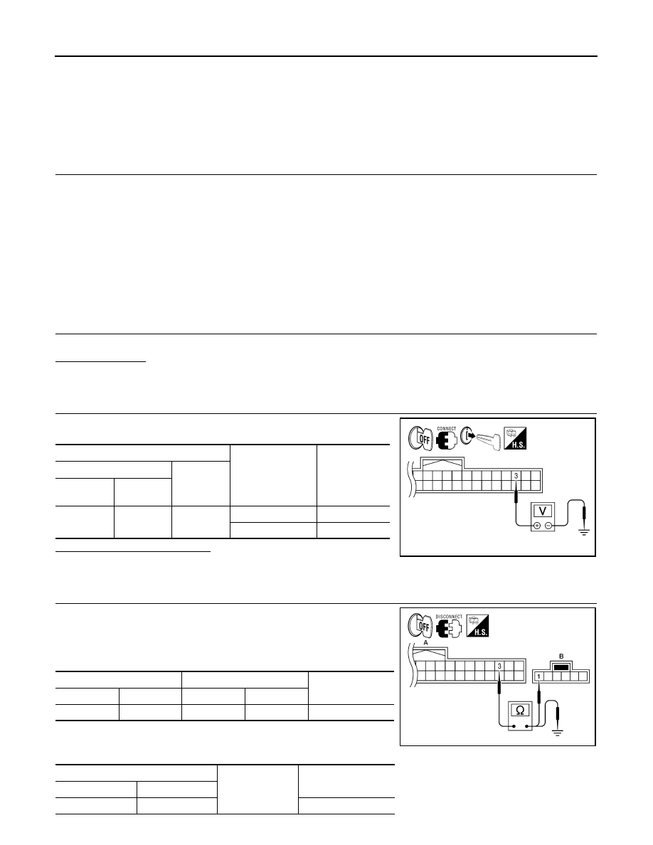
CHECK BCM INPUT SIGNAL
Check voltage between BCM harness connector and ground.
Is the inspection result normal?
YES
>> Inspection End.
NO
>> GO TO 3
3.
CHECK KEY SWITCH CIRCUIT
1.
Disconnect BCM and key switch and ignition knob switch con-
nectors.
2.
Check continuity between BCM harness connector M18 (A) and
key switch and ignition knob switch harness connector M32 (B).
3.
Check continuity between BCM harness connector M18 (A) and
ground.
KEY IN SW
When key is inserted into key cylinder
: ON
When key is removed from key cylinder
: OFF
Terminals
Condition
Voltage
(Approx.)
(+)
(
−
)
BCM
connector
Terminal
M18
3
Ground
Key is inserted
Battery voltage
Key is removed
0
AWNIA0269ZZ
A
B
Continuity
Connector
Terminal
Connector
Terminal
M18
3
M32
1
Yes
A
Ground
Continuity
Connector
Terminal
M18
3
No
AWNIA0270ZZ