содержание .. 1404 1405 1406 1407 ..
Nissan Tiida C11. Manual - part 1406
CONTROL LINKAGE
TM-675
< ON-VEHICLE REPAIR >
[6MT: RS6F94R]
C
E
F
G
H
I
J
K
L
M
A
B
TM
N
O
P
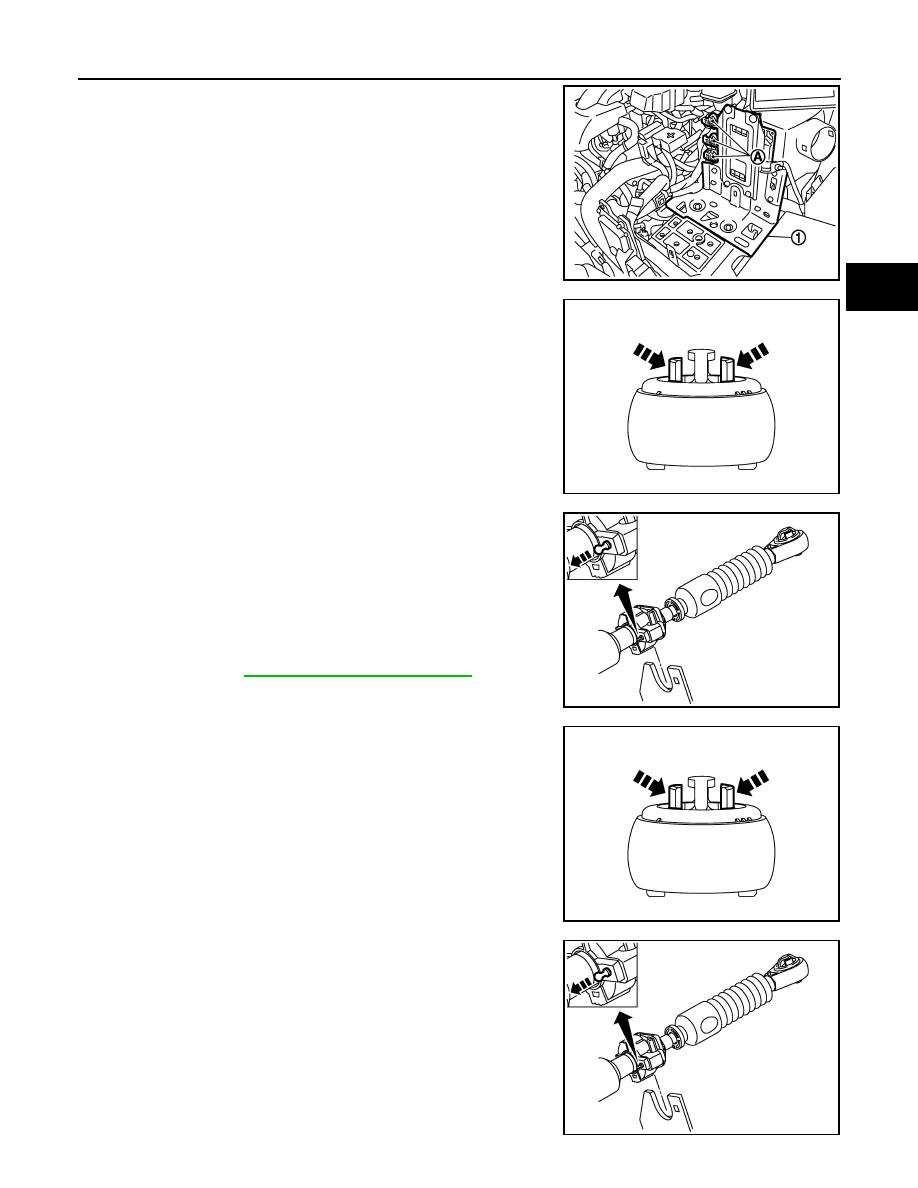
3.
Disconnect connectors (A) and then remove bracket (1).
4.
While pressing the lock of the select cable in the direction of the
arrow shown, remove the select cable from the selector lever.
5.
While pressing the lock of the shift cable in the direction of the
arrow shown, remove the shift cable from the shifter lever.
6.
While pulling the lock of the select cable in the direction of the
arrow shown, remove the select cable from the cable mounting
bracket.
7.
While pulling the lock of the shift cable in the direction of the
arrow shown, remove the shift cable from the cable mounting
bracket.
8.
Remove the control lever knob.
9.
Remove console finisher assembly and the center console
assembly. Refer to
IP-11, "Removal and Installation"
10. Shift the control lever to the neutral position.
11. While pressing the lock of the select cable in the direction of the
arrow shown, remove the select cable from the control device
assembly.
12. While pressing the lock of the shift cable in the direction of the
arrow shown, remove the shift cable from the control device
assembly.
13. While pulling the lock of the select cable in the direction of the
arrow shown, remove the select cable from the control device
assembly.
14. While pulling the lock of the shift cable in the direction of the
arrow shown, remove the shift cable from the control device
assembly.
15. Remove the control device assembly.
16. Remove the heat plate.
17. Remove the bracket.
JPDIA0240ZZ
JPDIC0066ZZ
JPDIC0067ZZ
JPDIC0066ZZ
JPDIC0067ZZ