Nissan Tiida C11. Manual - part 1389


  Главная      Nissan     Nissan Tiida C11 - Service Manual


поиск по сайту            


содержание   ..  1387  1388  1389  1390   ..


Nissan Tiida C11. Manual - part 1389


ASSEMBLY

TM-607

< DISASSEMBLY AND ASSEMBLY >

[TYPE 2 (4AT: RE4F03B)]

C

E

F

G

H

I

J

K

L

M

A

B

TM

N

O

P

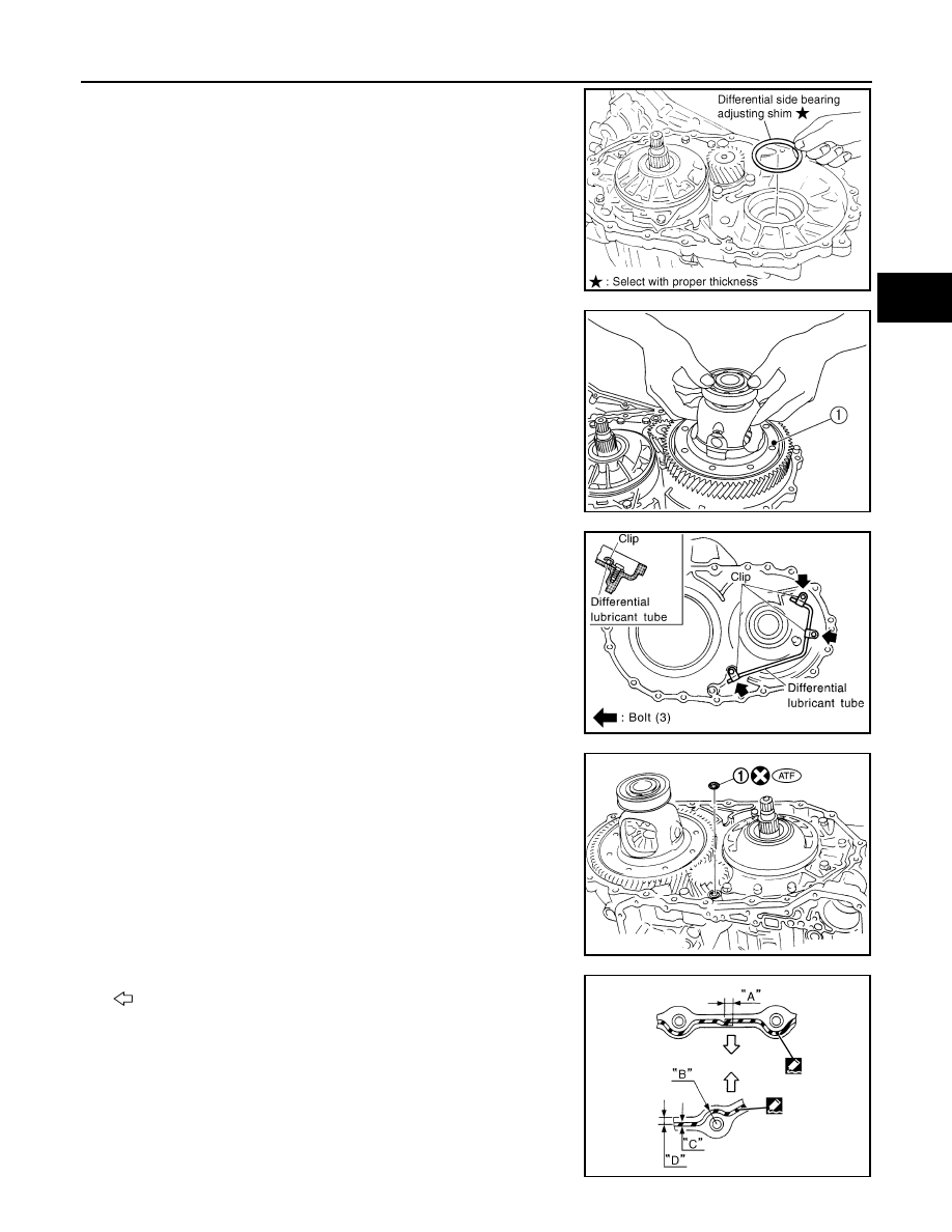
16. Install differential side bearing adjusting shim selected in differ-

ential side bearing end play adjustment step on transaxle case.

17. Install final drive assembly (1) on transaxle case.

18. Install differential lubricant tube and clips on converter housing.

19. Tighten differential lubricant tube fitting bolts to the specified

torque.

20. Install O-ring (1) on differential oil port of transaxle case as

shown.

21. Apply locking sealant (loctite #518) to transaxle case as shown.

: Inside of transaxle case

CAUTION:

SCIA4938E

SCIA6034J

SCIA3284E

SCIA5918J

“A”

: 3 - 5 mm (0.12 - 0.20 in)

“B”

: 8 mm (0.31 in) R

“C”

: 1.5 mm (0.059 in) dia.

“D”

: 4 mm (0.16 in)

SCIA7089E

TM-608

< DISASSEMBLY AND ASSEMBLY >

[TYPE 2 (4AT: RE4F03B)]

ASSEMBLY

Completely remove all moisture, oil and old sealant, etc. from the transaxle case and converter
housing mating surfaces.

22. Install converter housing on transaxle case.
23. Install bracket on converter housing.

24. Tighten converter housing bolts (1), (2) and (3) to the specified

torque.

*

: Tighten with bracket.

25. Install O-ring to plug.

CAUTION:

• Do not reuse O-ring.
• Apply ATF to O-ring.

26. Install plug to converter housing.

27. Tighten plug fitting bolt to the specified torque.

28. Install accumulator pistons.
a.

Install O-rings (1) on servo release accumulator piston (2) and
N-D accumulator piston (3). Refer to 

TM-321, "Accumulator"

.

b.

Install return springs (1), servo release accumulator piston (2)
and N-D accumulator piston (3) into transaxle case (4). Refer to

TM-321, "Accumulator"

.

29. Install lip seals (1) for band servo oil holes on transaxle case.

Bolt

1

2

3

*

Bolt length
[mm (in)]

30 (1.18)

40 (1.57)

Number of bolts

10

9

1

SCIA6956E

SCIA6033J

SCIA6042J

SCIA5895J

ASSEMBLY

TM-609

< DISASSEMBLY AND ASSEMBLY >

[TYPE 2 (4AT: RE4F03B)]

C

E

F

G

H

I

J

K

L

M

A

B

TM

N

O

P

30. Install control valve assembly on transaxle case.

a.

Install O-ring on terminal body.

CAUTION:

• Do not reuse O-ring.
• Apply ATF to O-ring.

b.

Insert manual valve into control valve assembly.

CAUTION:

Do not drop manual valve.

c.

Set manual shaft in “N” position.

d.

Install control valve assembly on transaxle case while aligning
manual valve (2) with manual plate (1).

e.

Install terminal body (2) into transaxle case by pushing it.

f.

Install snap ring (1) to terminal body (2).

g.

Tighten bolts (A), (B) and (C) to the specified torque.

Bolt length, number and location:

31. Install oil pan.
a.

Attach magnets on oil pan.

SCIA3999E

SCIA7090E

SCIA6030J

Bolt symbol

A

B

C

Bolt length “

” [mm (in)]

40.0 mm

(1.575 in)

33.0 mm

(1.299 in)

43.5 mm

(1.713 in)

Number of bolts

5

6

2

SCIA5911J

TM-610

< DISASSEMBLY AND ASSEMBLY >

[TYPE 2 (4AT: RE4F03B)]

ASSEMBLY

b.

Install oil pan gasket on transaxle case.

CAUTION:

• Completely remove all moisture, oil and old gasket, etc.

from the oil pan gasket mounting surface of transaxle
case.

• Do not reuse oil pan gasket.

c.

Install oil pan on transaxle case.

CAUTION:

Completely remove all moisture, oil and old gasket, etc.
from the oil pan gasket mounting surface of oil pan.

d.

Tighten oil pan bolts (1) to the specified torque.

CAUTION:

• Always replace oil pan bolts (1) as they are self-sealing bolts.
• Tighten four bolts in a criss-cross pattern to prevent dislocation of gasket.

e.

Install drain plug gasket and drain plug (2) to oil pan.

CAUTION:

Do not reuse drain plug gasket.

f.

Tighten drain plug to the specified torque.

32. Install PNP switch (2) on transaxle case.

: Bolt (3)

a.

Set manual shaft (1) in “P” position.

b.

Temporarily install PNP switch (2) on manual shaft (1).

c.

Set manual shaft (1) in “N” position.

d.

Use a 4 mm (0.16 in) dia. pin for this adjustment.

i.

Insert the pin straight into the manual shaft (1) adjustment hole.

ii.

Rotate PNP switch (2) until the pin can also be inserted straight
into hole in PNP switch (2).

e.

Tighten PNP switch fitting bolts to the specified torque.

f.

Remove pin from adjustment hole after adjusting PNP switch (2).

33. Install O-ring (3) to turbine revolution sensor (power train revolu-

tion sensor) (1).

34. Install turbine revolution sensor (power train revolution sensor)

(1) to transaxle case (2).

: Bolt

35. Tighten turbine revolution sensor (power train revolution sensor)

bolt to the specified torque.

36. Install revolution sensor (1) to transaxle case (2).

37. Tighten revolution sensor bolts to the specified torque.

: Bolt

CAUTION:

SCIA6050J

SCIA5904J

SCIA7004J

SCIA7170J


содержание   ..  1387  1388  1389  1390   ..