Nissan Tiida C11. Manual - part 1373


  Главная      Nissan     Nissan Tiida C11 - Service Manual


поиск по сайту            


содержание   ..  1371  1372  1373  1374   ..


Nissan Tiida C11. Manual - part 1373


REPAIR FOR COMPONENT PARTS

TM-543

< DISASSEMBLY AND ASSEMBLY >

[TYPE 2 (4AT: RE4F03B)]

C

E

F

G

H

I

J

K

L

M

A

B

TM

N

O

P

g.

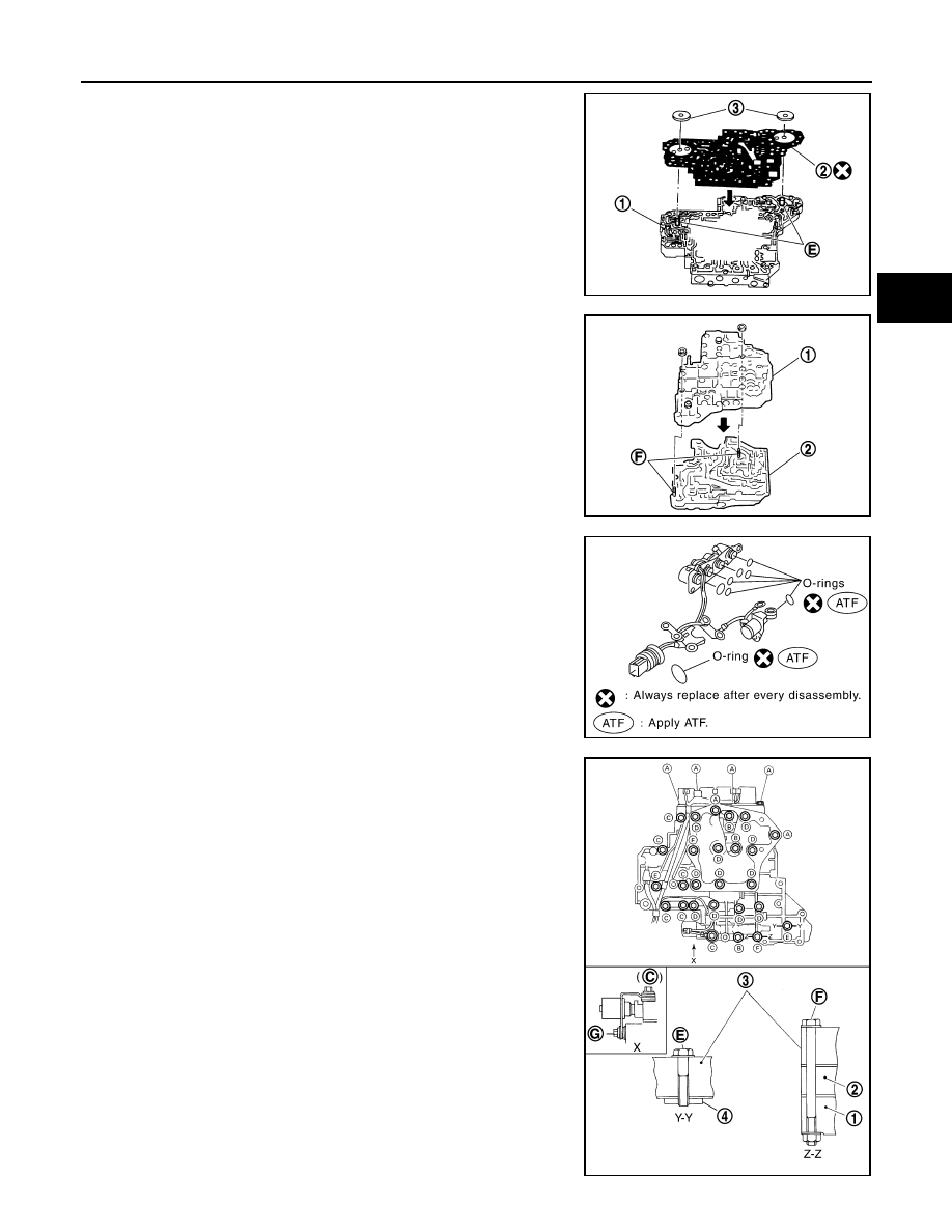
Install bolts (E) from bottom of control valve lower body (1).
Using bolts (E) as guides, install separating plate (2) as a set.

h.

Install support plates (3) on control valve lower body (1).

i.

Install control valve lower body (1) on control valve inter body (2)
using reamer bolts (F) as guides, and tighten reamer bolts (F)
slightly.

2.

Install O-rings on solenoid valves and terminal body.

3.

Install and tighten bolts.
(1): Control valve upper body
(2): Control valve inter body
(3): Control valve lower body
(4): Support plate

SCIA7013E

SCIA7014E

SCIA7180E

SCIA7058E

TM-544

< DISASSEMBLY AND ASSEMBLY >

[TYPE 2 (4AT: RE4F03B)]

REPAIR FOR COMPONENT PARTS

Bolt length, number and location:

*

: Reamer bolt and nut.

a.

Install and tighten bolts (B) to the specified torque.

b.

Install solenoid valve assembly (1) on control valve assembly.

c.

Tighten bolts (A), (C) and (G) to the specified torque.

d.

Remove reamer bolts (F), and then set oil strainer (1) on control
valve assembly 

e.

Install and tighten bolts (A), (D), reamer bolts (F) and nuts to the
specified torque.

f.

Tighten bolts (E) to the specified torque.

Bolt symbol

A

B

C

D

E

F

*

G

Bolt length “

” [mm (in)]

13.5 

(0.531)

58.0 

(2.283)

 40.0 

(1.575)

66.0 

(2.598)

33.0 

(1.299)

78.0 

(3.071)

18.0 

(0.709)

Number of bolts

6

3

6

11

2

2

1

Tightening torque
 [N·m (kg-m, in-lb)]

7.84 (0.80, 69)

3.92

(0.40, 35)

7.84 (0.80, 69)

Bolts:

7.84 N·m (0.80 kg-m, 69 in-lb)

ATL0032D

Bolts:

7.84 N·m (0.80 kg-m, 69 in-lb)

SCIA7008E

Nuts and bolts:

7.84 N·m (0.80 kg-m, 69 in-lb)

SCIA7131E

Bolts:

3.92 N·m (0.40 kg-m, 35 in-lb)

ATL0035D

REPAIR FOR COMPONENT PARTS

TM-545

< DISASSEMBLY AND ASSEMBLY >

[TYPE 2 (4AT: RE4F03B)]

C

E

F

G

H

I

J

K

L

M

A

B

TM

N

O

P

Control Valve Upper Body

INFOID:0000000001731438

COMPONENTS

1.

Retainer plate

2.

Plug

3.

Cooler check valve spring

4.

Cooler check valve

5.

Control valve upper body

6.

Pilot valve

7.

Pilot valve spring

8.

Retainer plate

9.

1-2 accumulator retainer plate

SCIA2960J

TM-546

< DISASSEMBLY AND ASSEMBLY >

[TYPE 2 (4AT: RE4F03B)]

REPAIR FOR COMPONENT PARTS

DISASSEMBLY

1.

Remove valves at retainer plates.

CAUTION:

Do not use a magnetic pick-up tool.

a.

Use suitable tool (A) to remove retainer plates (1).

b.

Remove retainer plates (1) while holding spring, plugs (2) or
sleeves using suitable tool (A).

CAUTION:

Remove plugs (2) slowly to prevent internal parts from
jumping out.

10. 1-2 accumulator piston spring

11.

1-2 accumulator piston

12. Plug

13. Retainer plate

14.

Retainer plate

15. Plug

16. 1st reducing valve

17.

1st reducing valve spring

18. Retainer plate

19. 3-2 timing valve spring

20.

3-2 timing valve

21. Retainer plate

22. Plug

23.

Overrun clutch reducing valve

24. Overrun clutch reducing valve spring

25. Retainer plate

26.

Torque converter relief valve spring 27. Torque converter relief valve

28. Retainer plate

29.

Sleeve

30. Plug

31. Torque converter clutch control valve 

spring

32.

Torque converter clutch control 
valve

33. Retainer plate

34. Plug

35.

1-2 accumulator valve spring

36. 1-2 accumulator valve

SCIA4979E

SCIA7136E

SCIA7137E


содержание   ..  1371  1372  1373  1374   ..