Nissan Tiida C11. Manual - part 1371


  Главная      Nissan     Nissan Tiida C11 - Service Manual


поиск по сайту            


содержание   ..  1369  1370  1371  1372   ..


Nissan Tiida C11. Manual - part 1371


REPAIR FOR COMPONENT PARTS

TM-535

< DISASSEMBLY AND ASSEMBLY >

[TYPE 2 (4AT: RE4F03B)]

C

E

F

G

H

I

J

K

L

M

A

B

TM

N

O

P

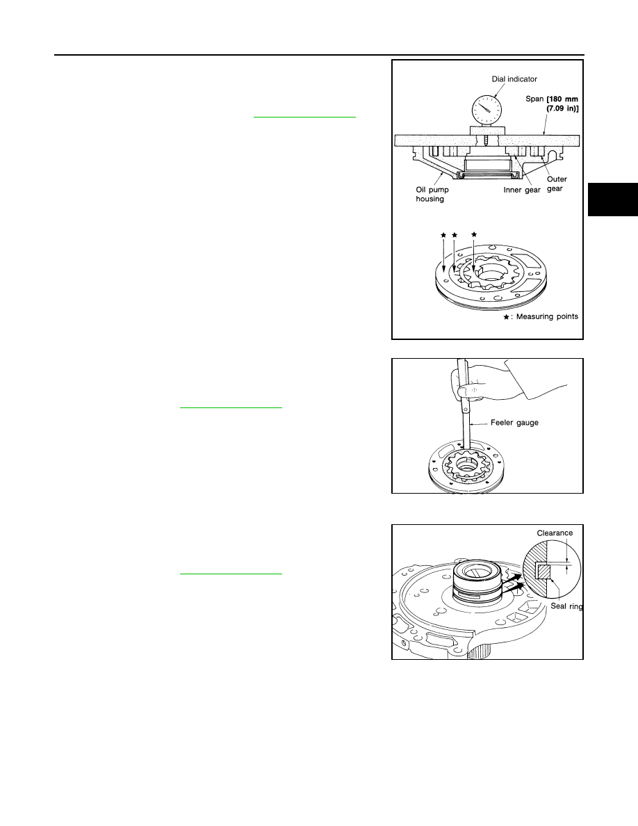
• Measure side clearance of inner gear and outer gear in at least

four places around each outside edge. Maximum measured values
should be within the specified clearance.

• If clearance is less than standard, select inner gear and outer gear

as a set so that clearance is within specifications.

• If clearance is more than standard, replace whole oil pump assem-

bly except oil pump cover.

• Measure clearance between outer gear and oil pump housing.

• If not within allowable limit, replace whole oil pump assembly

except oil pump cover.

Seal Ring Clearance

• Measure clearance between seal ring and ring groove.

• If not within allowable limit, replace oil pump cover assembly.

ASSEMBLY

Standard clearance:

Refer to 

TM-323, "Oil Pump"

.

SCIA4957E

Standard clearance and allowable limit:

Refer to 

TM-323, "Oil Pump"

.

SAT096D

Standard clearance and allowable limit:

Refer to 

TM-323, "Oil Pump"

.

SAT097D

TM-536

< DISASSEMBLY AND ASSEMBLY >

[TYPE 2 (4AT: RE4F03B)]

REPAIR FOR COMPONENT PARTS

1.

Install oil pump housing oil seal on oil pump housing.

CAUTION:

• Do not reuse oil pump housing oil seal.
• Apply ATF to outer surface of oil pump housing oil seal.

2.

Install inner gear and outer gear on oil pump housing.

CAUTION:

Be careful with the direction of inner gear.

3.

Install oil pump cover on oil pump housing.

a.

Wrap masking tape around splines of oil pump cover assembly
to protect seal. Position oil pump cover assembly on oil pump
housing assembly, then remove masking tape.

b.

Tighten oil pump cover fitting bolts in the order as shown, and
then tighten them to the specified torque in the same order.

4.

Install seal rings (1) to oil pump assembly (2) carefully after
packing ring groove with petroleum jelly.

CAUTION:

Do not spread gap of seal rings (1) excessively while install-
ing. The seal rings (1) may be deformed.

Control Valve Assembly

INFOID:0000000001731437

COMPONENTS

SAT900DA

SAT092D

SAT101D

SCIA7016E

REPAIR FOR COMPONENT PARTS

TM-537

< DISASSEMBLY AND ASSEMBLY >

[TYPE 2 (4AT: RE4F03B)]

C

E

F

G

H

I

J

K

L

M

A

B

TM

N

O

P

DISASSEMBLY

Place control valve assembly with control valve upper body (1) side
down. Remove bolts (A) to (G), reamer bolts (F), nuts and support
plates (4) according to the following procedures. Separate control
valve upper body (1), control valve inter body (2) and control valve
lower body (3).

1.

Pilot filter

2.

Control valve upper body

3.

Steel ball

4.

Separating plate

5.

Control valve inter body

6.

Steel ball

7.

Support plate

8.

Separating plate

9.

Control valve lower body

10. Line pressure relief valve spring

11.

Check ball

12. Torque converter pressure holding 

spring

13. Solenoid valve assembly

14. Terminal body

15. O-ring

16. O-ring

17. O-ring

18. Oil strainer

SCIA5967J

SCIA7058E

TM-538

< DISASSEMBLY AND ASSEMBLY >

[TYPE 2 (4AT: RE4F03B)]

REPAIR FOR COMPONENT PARTS

Bolt length, number and location:

*

: Reamer bolt and nut.

1.

Remove bolts (A), (D), reamer bolt (F) and nut, and remove oil
strainer (1) from control valve assembly.

2.

Remove bolts (A), (C) and (G), and then remove solenoid valve
assembly (1) from control valve assembly.

3.

Remove O-rings from solenoid valves and terminal body.

4.

Place control valve upper body face down, and remove bolts
(B), reamer bolt (F) and nut.

CAUTION:

Remove bolts with control valve upper body facing down,
because control valve upper body and control valve inter
body may come off and steel ball may fall and be lost.

Bolt symbol

A

B

C

D

E

F

*

G

Bolt length “

” [mm (in)]

13.5 

(0.531)

58.0 

(2.283)

 40.0 

(1.575)

66.0 

(2.598)

33.0 

(1.299)

78.0 

(3.071)

18.0 

(0.709)

Number of bolts

6

3

6

11

2

2

1

SCIA7007E

SCIA7008E

SCIA7180E

ATL0020D


содержание   ..  1369  1370  1371  1372   ..