содержание .. 1358 1359 1360 1361 ..
Nissan Tiida C11. Manual - part 1360
TRANSMISSION CONTROL MODULE
TM-491
< ON-VEHICLE REPAIR >
[TYPE 2 (4AT: RE4F03B)]
C
E
F
G
H
I
J
K
L
M
A
B
TM
N
O
P
ON-VEHICLE REPAIR
TRANSMISSION CONTROL MODULE
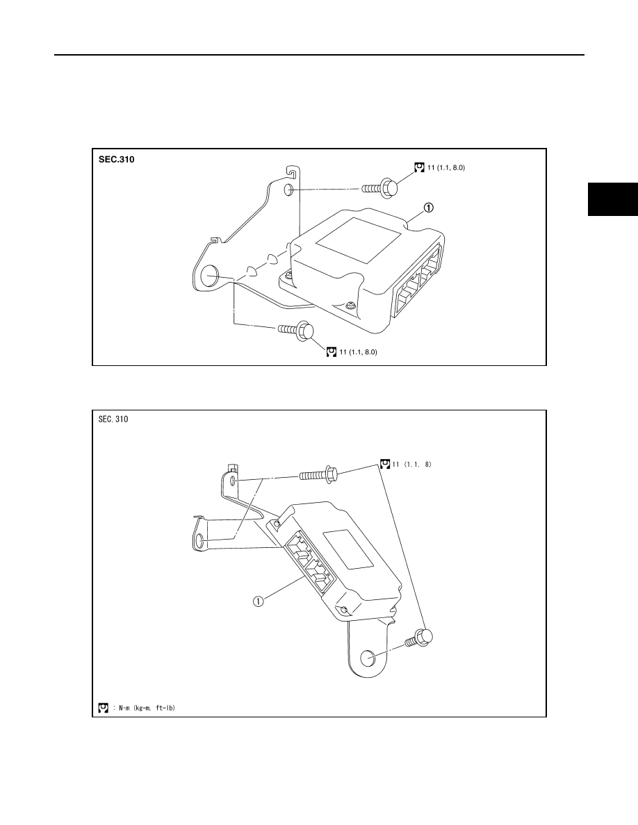
Exploded View
INFOID:0000000001731415
LHD MODELS
RHD MODELS
Removal and Installation
INFOID:0000000001731416
NOTE:
SCIA6963E
1.
TCM
SCIA6092J
1.
TCM