Nissan Tiida C11. Manual - part 1331


  Главная      Nissan     Nissan Tiida C11 - Service Manual


поиск по сайту            


содержание   ..  1329  1330  1331  1332   ..


Nissan Tiida C11. Manual - part 1331


TORQUE CONVERTER CLUTCH SOLENOID VALVE

TM-375

< COMPONENT DIAGNOSIS >

[TYPE 2 (4AT: RE4F03B)]

C

E

F

G

H

I

J

K

L

M

A

B

TM

N

O

P

4.

CHECK VALVE RESISTANCE

1.

Turn ignition switch OFF.

2.

Disconnect terminal cord assembly connector in engine room.

3.

Check resistance between terminal cord assembly harness con-
nector terminal and ground.

OK or NG

OK

>> GO TO 5.

NG

>> Repair or replace damaged parts.

5.

CHECK DTC

Perfor

TM-373, "DTC Confirmation Procedure"

.

OK or NG

OK

>> INSPECTION END

NG

>> GO TO 6.

6.

CHECK TCM

1.

Check TCM input/output signals. Refer to 

XX-XX, "*****"

.

2.

If NG, recheck TCM pin terminals for damage or loose connection with harness connector.

OK or NG

OK

>> INSPECTION END

NG

>> Repair or replace damaged parts.

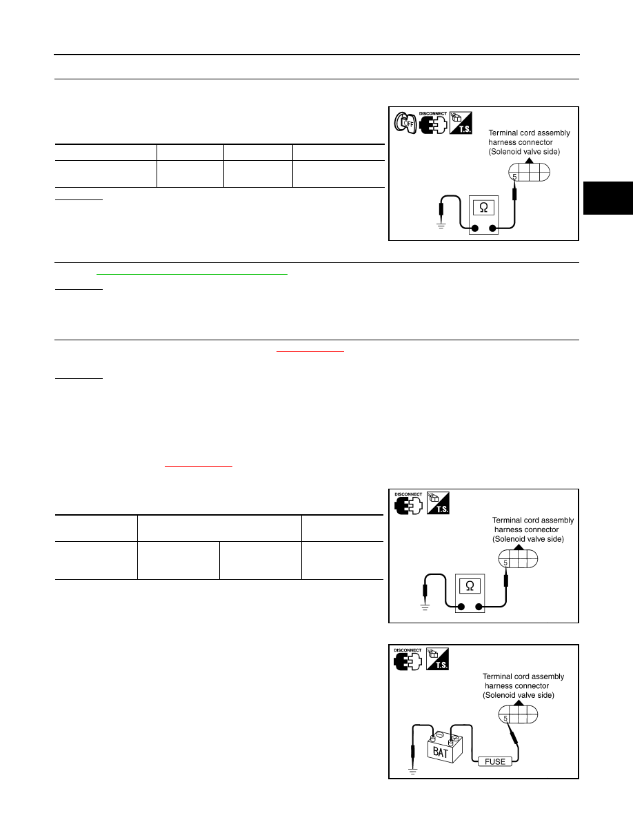
Component Inspection

INFOID:0000000001713033

TORQUE CONVERTER CLUTCH SOLENOID VALVE

• For removal, refer to 

XX-XX, "*****"

.

Resistance Check

• Check resistance between terminal and ground.

Operation Check

• Check solenoid valve by listening for its operating sound while

applying battery voltage to the terminal and ground.

Solenoid valve

Connector

Terminal

Resistance (Approx.) 

Torque converter clutch 
solenoid valve

F30

5 - Ground

5 - 20 

SCIA4946E

Solenoid valve

Terminal

Resistance (Ap-

prox.)

Torque converter 
clutch solenoid 
valve

5

Ground

5 - 20 

SCIA2063E

SCIA2066E

TM-376

< COMPONENT DIAGNOSIS >

[TYPE 2 (4AT: RE4F03B)]

BATT/FLUID TEMP SEN (A/T FLUID TEMP SENSOR CIRCUIT AND TCM POW-

ER SOURCE)

BATT/FLUID TEMP SEN (A/T FLUID TEMP SENSOR CIRCUIT AND TCM
POWER SOURCE)

Description

INFOID:0000000001713034

The A/T fluid temperature sensor detects the A/T fluid temperature and sends the signal to the TCM.

CONSULT-III Reference Value in Data Monitor Mode

INFOID:0000000001713035

Remarks: Specification data are reference values.

On Board Diagnosis Logic

INFOID:0000000001713036

Diagnostic trouble code “BATT/FLUID TEMP SEN” with CONSULT-III or 8th judgement flicker without CON-
SULT-III is detected when TCM receives an excessively low or high voltage from the sensor.

Possible Cause

INFOID:0000000001713037

• Harness or connector

(Sensor circuit is open or shorted.)

• A/T fluid temperature sensor

DTC Confirmation Procedure

INFOID:0000000001713038

CAUTION:

• Always drive vehicle at a safe speed.
• If performing this “DTC Confirmation Procedure” again, always turn ignition switch OFF and wait at

least 10 seconds before continuing.

After the repair, perform the following procedure to confirm the malfunction is eliminated.

 WITH CONSULT-III

1.

Start engine.

2.

Select “DATA MONITOR” mode for “TRANSMISSION” with CONSULT-III.

3.

Touch “START”.

4.

Drive vehicle under the following conditions.
SLCT LVR POSI: “D” position
VEHICLE SPEED: Higher than 20 km/h (12 MPH)

5.

If the check result is NG, go to 

TM-376, "Diagnosis Procedure"

.

 WITHOUT CONSULT-III

1.

Start engine.

2.

Drive vehicle under the following conditions.
Selector lever position: “D” position
Vehicle speed: Higher than 20 km/h (12 MPH)

3.

Perform self-diagnosis. Refer to 

TM-350, "Diagnosis Procedure without CONSULT-III"

.

4.

If the check result is NG, go to 

TM-376, "Diagnosis Procedure"

.

Diagnosis Procedure

INFOID:0000000001713040

1.

CHECK TCM POWER SOURCE

1.

Turn ignition switch ON. (Do not start engine.)

Item name

Condition

Display value (Approx.)

FLUID TEMP SE 

When A/T fluid temperature is 20

°

C (68

°

F).

1.5V

When A/T fluid temperature is 80

°

C (176

°

F).

0.5V

BATT/FLUID TEMP SEN (A/T FLUID TEMP SENSOR CIRCUIT AND TCM POW-

ER SOURCE)

TM-377

< COMPONENT DIAGNOSIS >

[TYPE 2 (4AT: RE4F03B)]

C

E

F

G

H

I

J

K

L

M

A

B

TM

N

O

P

2.

Check voltage between TCM connector terminal and ground.

3.

Turn ignition switch OFF.

4.

Check voltage between TCM connector terminal and ground.

OK or NG

OK

>> GO TO 3.

NG

>> GO TO 2.

2.

DETECT MALFUNCTIONING ITEM

Check the following items:
• Harness for short or open between ignition switch and TCM terminals 10, 19
• Harness for short or open between battery and TCM terminal 28
• 10A fuse (No.13, located in the fuse block) and 10A fuse (No.49, located in the IPDM E/R) 
• Ignition switch.

OK or NG

OK

>> GO TO 9.

NG

>> Repair or replace damaged parts.

3.

CHECK INPUT SIGNAL OF A/T FLUID TEMPERATURE SENSOR

With CONSULT-III

1.

Start engine.

2.

Select “TCM INPUT SIGNALS” in “DATA MONITOR” mode for “TRANSMISSION” with CONSULT-III.

3.

Read out the value of “FLUID TEMP SE”.

Without CONSULT-III

1.

Start engine.

Item

Connector

Terminal

Judgement standard (Ap-

prox.)

Power supply

E31

10

Battery voltage

19

Battery voltage

Power supply

(memory back-up)

E32

28

Battery voltage

SCIA2656E

Item

Connector

Terminal

Judgement standard (Approx.)

Power supply

E31

10

0V

19

0V

Power supply

(memory back-up)

E32

28

Battery voltage

SCIA2657E

Item name

Condition

Display value 
(Approx.)

FLUID TEMP 
SE

When A/T fluid temperature is 20

°

C (68

°

F).

1.5V

When A/T fluid temperature is 80

°

C (176

°

F).

0.5V

TM-378

< COMPONENT DIAGNOSIS >

[TYPE 2 (4AT: RE4F03B)]

BATT/FLUID TEMP SEN (A/T FLUID TEMP SENSOR CIRCUIT AND TCM POW-

ER SOURCE)

2.

Check voltage TCM connector terminals while warming up A/T.

OK or NG

OK

>> GO TO 9.

NG

>> GO TO 4.

4.

DETECT MALFUNCTIONING ITEM

Check the following items:
• Harness for short or open between TCM, ECM and terminal cord assembly
• Ground circuit for ECM.

OK or NG

OK

>> GO TO 5.

NG

>> Repair or replace damaged parts.

5.

 CHECK FLUID TEMPERATURE SENSOR CIRCUIT

1.

Turn ignition switch OFF.

2.

Disconnect the TCM connector.

3.

Check resistance between TCM connector terminals.

 OK or NG

 OK 

>> GO TO 9.

 NG

>> GO TO 6.

6.

 CHECK HARNESS BETWEEN TCM AND TERMINAL CORD ASSEMBLY HARNESS CONNECTOR

1.

Turn ignition switch OFF.

2.

Disconnect terminal cord assembly harness connector and TCM connector.

3.

Check continuity between terminal cord assembly harness con-
nector terminals and TCM connector terminals.

4.

If OK, check harness for short to ground and short to power.

5.

If OK, check continuity between ground and transaxle assembly.

6.

Reinstall any part removed.

OK or NG

OK

>> GO TO 7.

NG

>> Repair open circuit or short to ground or short to power in harness or connectors.

Item

Connector

Terminal

Condition

Judgement 

standard 

(Approx.)

A/T fluid 
temperature 
sensor

E32

47 - 42

When A/T fluid tempera-
ture is 20

°

C (68

°

F).

1.5V

When A/T fluid tempera-
ture is 80

°

C (176

°

F).

0.5V

SCIA2658E

Item

Connector

Terminal

Tempera-

ture 

°

C (

°

F)

Resistance 

(Approx.)

A/T fluid 
temperature 
sensor

E32

47 - 42

20 (68)

2.5 k

80 (176)

0.3 k

SCIA4947E

Item

Connector

Terminal

Continuity

TCM

E32

42

Yes

Terminal cord assembly 
harness connector

F30

7

TCM

E32

47

Yes

Terminal cord assembly 
harness connector

F30

6

SCIA2660E


содержание   ..  1329  1330  1331  1332   ..