Nissan Tiida C11. Manual - part 1319


  Главная      Nissan     Nissan Tiida C11 - Service Manual


поиск по сайту            


содержание   ..  1317  1318  1319  1320   ..


Nissan Tiida C11. Manual - part 1319


DIAGNOSIS AND REPAIR WORKFLOW

TM-327

< BASIC INSPECTION >

[TYPE 2 (4AT: RE4F03B)]

C

E

F

G

H

I

J

K

L

M

A

B

TM

N

O

P

>> GO TO 3.

3.

ROAD TEST

Perform “ROAD TEST”. Refer to 

TM-482, "Description"

.

>> GO TO 4.

4.

PERFORM SELF-DIAGNOSTIC PROCEDURE

Perform “Self-Diagnosis Procedure”. Refer to 

TM-348, "CONSULT-III Function (TRANSMISSION)"

 or 

TM-350,

"Diagnosis Procedure without CONSULT-III"

.

>> GO TO 5.

5.

CHECK SYMPTOM 2

Try to confirm the symptom described by the customer.

Is any malfunction present?

YES

>> GO TO 6.

NO

>> INSPECTION END

6.

CHECK SYMPTOM 3

Try to confirm the symptom described by the customer.

Is any malfunction present?

YES

>> GO TO 2.

NO

>> INSPECTION END

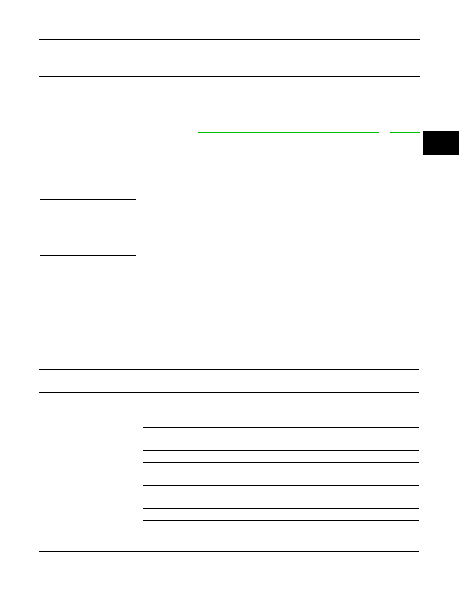
Diagnostic Work Sheet

INFOID:0000000001728327

INFORMATION FROM CUSTOMER

KEY POINTS

• WHAT..... Vehicle and A/T model
• WHEN..... Date, Frequencies
• WHERE..... Road conditions
• HOW..... Operating conditions, Symptoms

DIAGNOSTIC WORK SHEET

Customer name

MR/MS

Model and Year

VIN

Trans. Model

Engine

Mileage

Malfunction Date

Manuf. Date

In Service Date

Frequency

 Continuous

 Intermittent (

times a day)

Symptoms

 Vehicle does not move.

(

 Any position

 Particular position)

 No up-shift

(

 1st 

 2nd

 2nd 

 3rd

 3rd 

 4th   

 4th 

 5th)

 No down-shift

(

 5th 

 4th   

 4th 

 3rd

 3rd 

 2nd

 2nd 

 1st)

 Lock-up malfunction

 Shift point too high or too low.

 Shift shock or slip

(

 N 

 D

 N 

 R

 Lock-up

 Any drive position)

 Noise or vibration

 No kick down

 No pattern select

 Others

(

)

Malfunction indicator lamp (MIL)

 Continuously lit

 Not lit

TM-328

< BASIC INSPECTION >

[TYPE 2 (4AT: RE4F03B)]

DIAGNOSIS AND REPAIR WORKFLOW

1

 Read the item on cautions concerning fail-safe and understand the customer's com-

plaint.

TM-426

2

 A/T fluid inspection, stall test and line pressure test

 A/T fluid inspection

TM-473

 Leak (Repair leak location.)

 State

 Amount

3

 Stall test

TM-477

 Torque converter one-way clutch

 Front brake

 High and low reverse clutch

 Low coast brake

 Forward brake

 Reverse brake

 Forward one-way clutch

 1st one-way 

clutch

 3rd one-way 

clutch

 Engine

 Line pressure low

 Except for input 

clutch and direct 
clutch, clutches and 
brakes OK

 Line pressure test - Suspected part:

TM-480

4

 Perform self-diagnosis. — Check detected items to repair or replace malfunctioning 

part.

TM-348

 or 

TM-350

5

 Perform road test.

5-1

 Check before engine is started

TM-482

5-2

 Check at idle

TM-483

5-3

Cruise test

 Part 1

TM-485

 Part 2

TM-487

 Part 3

TM-488

 Check malfunction phenomena to repair or replace malfunctioning part after completing all road test.

Refer to 

TM-429

.

5

 Drive vehicle to check that the malfunction phenomenon has been resolved.

6

 Erase the results of the self-diagnosis from the TCM and the ECM.

TM-348

 or 

TM-350

A/T CONTROL SYSTEM

TM-329

< FUNCTION DIAGNOSIS >

[TYPE 2 (4AT: RE4F03B)]

C

E

F

G

H

I

J

K

L

M

A

B

TM

N

O

P

FUNCTION DIAGNOSIS

A/T CONTROL SYSTEM

Cross-Sectional View

INFOID:0000000001714309

1.

Converter housing

2.

Oil pump

3.

Brake band

4.

Reverse clutch

5.

High clutch

6.

Front planetary gear

7.

Low one-way clutch

8.

Rear planetary gear

9.

Forward clutch

10. Overrun clutch

11.

Low & reverse brake

12. Output gear

13. Band servo piston

14. Reverse clutch drum

15. Side cover

16. Idler gear 

17. Forward one-way clutch

18. Transaxle case

19. Reduction pinion gear

20. Final gear

21. Differential case

22. Input shaft

23. Torque converter

SCIA6171J

TM-330

< FUNCTION DIAGNOSIS >

[TYPE 2 (4AT: RE4F03B)]

A/T CONTROL SYSTEM

Shift Mechanism

INFOID:0000000001714310

CONSTRUCTION

FUNCTION OF CLUTCH AND BRAKE

CLUTCH AND BAND CHART

1.

Torque converter

2.

Oil pump

3.

Input shaft

4.

Brake band

5.

Reverse clutch

6.

High clutch

7.

Front sun gear

8.

Front pinion gear

9.

Front internal gear

10. Front planetary carrier

11.

Rear sun gear

12. Rear pinion gear

13. Rear internal gear

14. Rear planetary carrier

15. Forward clutch

16. Forward one-way clutch

17. Overrun clutch

18. Low one-way clutch

19. Low & reverse brake

20. Parking pawl

21. Parking gear

22. Output shaft

23. Idle gear

24. Output gear

SAT998I

Clutch and brake components

Abbr.

Function

5

Reverse clutch

R/C

To transmit input power to front sun gear 7.

6

High clutch

H/C

To transmit input power to front planetary carrier 10.

15

Forward clutch

F/C

To connect front planetary carrier 10 with forward one-way clutch 16.

17

Overrun clutch

O/C

To connect front planetary carrier 10 with rear internal gear 13.

4

Brake band

B/B

To lock front sun gear 7.

16

Forward one-way clutch

F/O.C

When forward clutch 15 is engaged, to stop rear internal gear 13 from rotating in 
opposite direction against engine revolution.

18

Low one-way clutch

L/O.C

To stop front planetary carrier 10 from rotating in opposite direction against en-
gine revolution.

19

Low & reverse brake

L & R/B

To lock front planetary carrier 10.

Shift posi-

tion

R/C

5

H/C

6

F/C

15

O/C

17

Band servo

F/O.C

16

L/O.C

18

L&R/B

19

Lock-

up

Remarks

2nd 

apply

3rd re-

lease

4th ap-

ply

P

PARK

POSITION

R

REVERSE 
POSITION


содержание   ..  1317  1318  1319  1320   ..