содержание .. 1316 1317 1318 1319 ..
Nissan Tiida C11. Manual - part 1318
SERVICE DATA AND SPECIFICATIONS (SDS)
TM-323
< SERVICE DATA AND SPECIFICATIONS (SDS)
[TYPE 1 (4AT: RE4F03B)]
C
E
F
G
H
I
J
K
L
M
A
B
TM
N
O
P
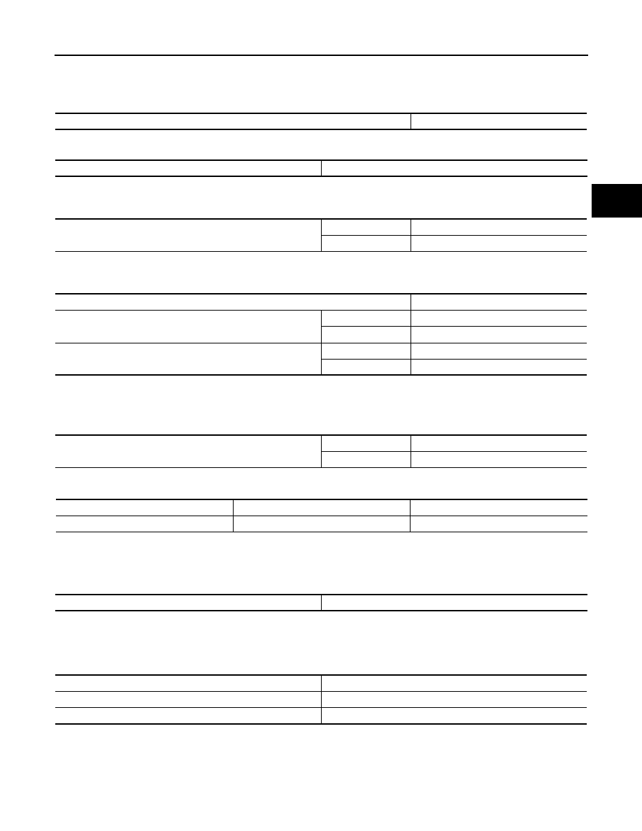
Final Drive
INFOID:0000000001731396
DIFFERENTIAL SIDE GEAR CLEARANCE
DIFFERENTIAL SIDE BEARING END PLAY
Planetary Carrier
INFOID:0000000001731397
Oil Pump
INFOID:0000000001731398
Input Shaft
INFOID:0000000001731399
SEAL RING CLEARANCE
SEAL RING
Unit: mm (in)
Reduction Pinion Gear
INFOID:0000000001731400
TURNING TORQUE
Band Servo
INFOID:0000000001731401
RETURN SPRINGS
Unit: mm (in)
Output Shaft
INFOID:0000000001731402
SEAL RING CLEARANCE
Clearance between side gear and differential case with washer [mm (in)]
0.1 - 0.2 (0.004 - 0.008)
Differential side bearing end play [mm (in)]
0 - 0.15 (0 - 0.0059)
Clearance between planetary carrier and pinion washer [mm (in)]
Standard
0.15 - 0.70 (0.0059 - 0.0276)
Allowable limit
0.80 (0.0315)
Oil pump side clearance
0.02 - 0.04 (0.0008 - 0.0016)
Clearance between oil pump housing and outer gear [mm (in]
Standard
0.08 - 0.15 (0.0031 - 0.0059)
Allowable limit
0.15 (0.0059)
Oil pump cover seal ring clearance [mm (in)]
Standard
0.10 - 0.25 (0.0039 - 0.0098)
Allowable limit
0.25 (0.0098)
Input shaft seal ring clearance [mm (in)]
Standard
0.10 - 0.25 (0.0039 - 0.0098)
Allowable limit
0.25 (0.098)
Outer diameter
Inner diameter
Width
24 (0.94)
20.4 (0.803)
1.97 (0.0776)
Turning torque of reduction pinion gear [N·m (kg-m, in-lb)]
0.11 - 0.69 (0.02 - 0.07, 1 - 6)
Return spring
Free length
2nd servo return spring
32.5 (1.280)
OD servo return spring
38.52 (1.5165)