Nissan Tiida C11. Manual - part 1294


  Главная      Nissan     Nissan Tiida C11 - Service Manual


поиск по сайту            


содержание   ..  1292  1293  1294  1295   ..


Nissan Tiida C11. Manual - part 1294


DISASSEMBLY

TM-227

< DISASSEMBLY AND ASSEMBLY >

[TYPE 1 (4AT: RE4F03B)]

C

E

F

G

H

I

J

K

L

M

A

B

TM

N

O

P

d.

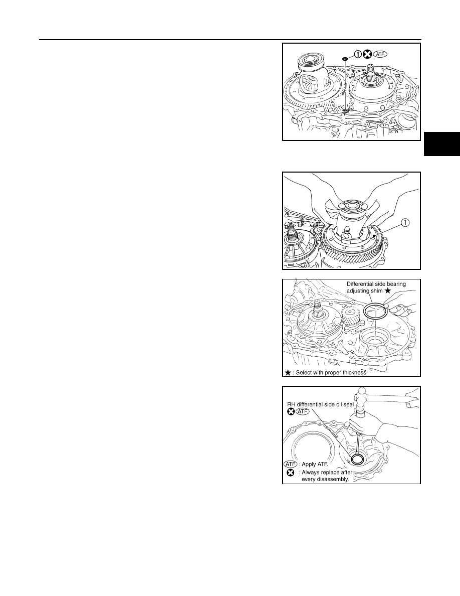
Remove O-ring (1) from differential lubricant hole.

23. Remove plug from converter housing.
24. Remove O-ring from plug.

25. Remove final drive assembly (1) from transaxle case.

26. Remove differential side bearing adjusting shim from transaxle

case.

27. Remove RH differential side oil seal from converter housing

using suitable tool.

CAUTION:

Do not scratch converter housing.

SCIA5918J

SCIA6034J

SCIA4938E

SCIA3283E

TM-228

< DISASSEMBLY AND ASSEMBLY >

[TYPE 1 (4AT: RE4F03B)]

DISASSEMBLY

28. Remove differential lubricant tube and clips from converter

housing.

29. Remove oil pump assembly according to the following procedures.
a.

Remove O-ring from input shaft assembly (high clutch drum).

b.

Remove oil pump assembly fitting bolts, and then remove oil
pump assembly (1) from transaxle case.

c.

Remove O-ring from oil pump assembly (1).

d.

Remove bearing race (1) and thrust washer (2) from oil pump
assembly (3).

SCIA3284E

SCIA5634E

SCIA6036J

SCIA6957E

DISASSEMBLY

TM-229

< DISASSEMBLY AND ASSEMBLY >

[TYPE 1 (4AT: RE4F03B)]

C

E

F

G

H

I

J

K

L

M

A

B

TM

N

O

P

30. Remove brake band according to the following procedures.

a.

Loosen lock nut (1), and then remove anchor end pin (2) and
lock nut (1) as a set from transaxle case.

b.

Remove brake band from transaxle case.

• To prevent brake linings from cracking or peeling, do not

stretch the flexible band unnecessarily. When removing
brake band, always secure it with a clip as shown.
Leave the clip in position after removing brake band.

c.

Check brake band facing for damage, cracks, wear or burns.

31. Remove input shaft assembly (high clutch assembly) and

reverse clutch assembly according to the following procedures.

a.

Remove input shaft assembly (high clutch assembly) (1) with
reverse clutch assembly (2).

SCIA6037J

SAT038D

SAT039D

SAT040D

SCIA6038J

TM-230

< DISASSEMBLY AND ASSEMBLY >

[TYPE 1 (4AT: RE4F03B)]

DISASSEMBLY

b.

Remove input shaft assembly (high clutch assembly) (1) from
reverse clutch assembly (2).

c.

Remove needle bearing (1) from input shaft assembly (high
clutch drum) (2).
• Inspect needle bearing (1) and input shaft assembly (high

clutch drum) (2), and replace if damaged or worn.

32. Remove needle bearing from high clutch hub.

• Inspect needle bearing, and replace if damaged or worn.

33. Remove high clutch hub from front sun gear.

• Inspect high clutch hub, and replace if damaged or worn.

34. Remove needle bearing from front sun gear.

• Inspect needle bearing, and replace if damaged or worn.

SCIA6958E

SCIA6959E

SAT371D

SAT370D

SAT369D


содержание   ..  1292  1293  1294  1295   ..