Nissan Tiida C11. Manual - part 128


  Главная      Nissan     Nissan Tiida C11 - Service Manual


поиск по сайту            


содержание   ..  126  127  128  129   ..


Nissan Tiida C11. Manual - part 128


CO-30

< SYMPTOM DIAGNOSIS >

[MR18DE]

OVERHEATING CAUSE ANALYSIS

SYMPTOM DIAGNOSIS

OVERHEATING CAUSE ANALYSIS

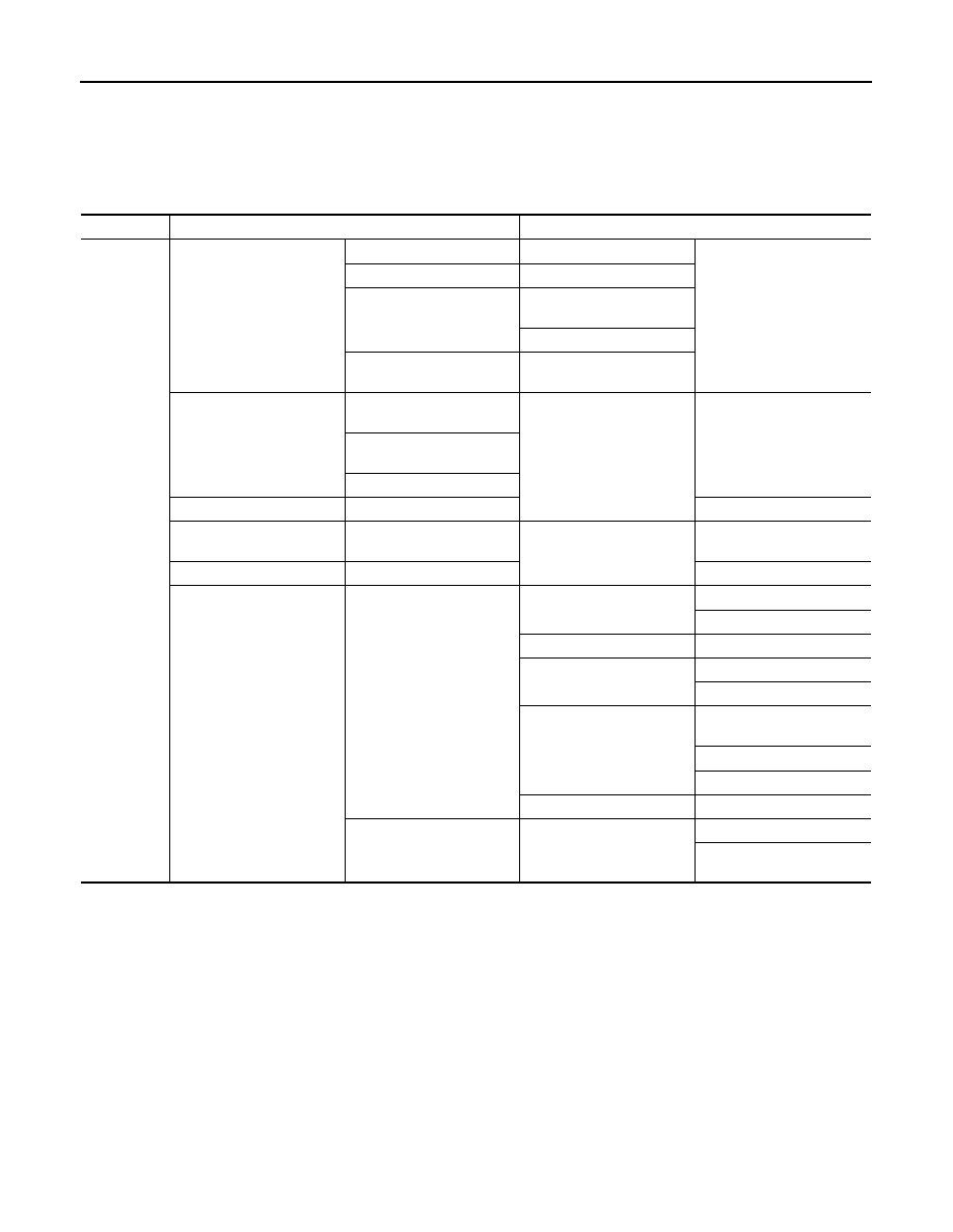
Troubleshooting Chart

INFOID:0000000001337836

Symptom

Check items

Cooling sys-
tem parts 
malfunction

Poor heat transfer

Water pump malfunction

Worn or loose drive belt

Thermostat stuck closed

Thermostat

Damaged fins

Dust contamination or pa-
per clogging

Physical damage

Clogged radiator cooling 
tube

Excess foreign material 
(rust, dirt, sand, etc.)

Reduced air flow

Cooling fan does not oper-
ate

Fan assembly

High resistance to fan rota-
tion

Damaged fan blades

Damaged radiator shroud

Improper engine coolant 
mixture ratio

Engine coolant viscosity

Poor engine coolant quality

Insufficient engine coolant

Engine coolant leaks

Cooling hose

Loose clamp

Cracked hose

Water pump

Poor sealing

Radiator cap

Loose

Poor sealing

Radiator

O-ring for damage, deterio-
ration or improper fitting

Cracked radiator tank

Cracked radiator core

Reservoir tank

Cracked reservoir tank

Overflowing reservoir tank

Exhaust gas leaks into cool-
ing system

Cylinder head deterioration

Cylinder head gasket deteri-
oration

OVERHEATING CAUSE ANALYSIS

CO-31

< SYMPTOM DIAGNOSIS >

[MR18DE]

C

D

E

F

G

H

I

J

K

L

M

A

CO

N

P

O

Except cool-
ing system 
parts mal-
function

Overload on engine

Abusive driving

High engine rpm under no 
load

Driving in low gear for ex-
tended time

Driving at extremely high 
speed

Power train system mal-
function

Installed improper size 
wheels and tires

Dragging brakes

Improper ignition timing

Blocked or restricted air 
flow

Blocked bumper

Installed front bumper fas-

cia cover

Blocked radiator grille

Mud contamination or paper 
clogging

Blocked radiator

Blocked air flow

Blocked condenser

Installed large fog lamp

Symptom

Check items

CO-32

< PRECAUTION >

[MR18DE]

PRECAUTIONS

PRECAUTION

PRECAUTIONS

Precaution for Supplemental Restraint System (SRS) "AIR BAG" and "SEAT BELT 
PRE-TENSIONER"

INFOID:0000000001516585

The Supplemental Restraint System such as “AIR BAG” and “SEAT BELT PRE-TENSIONER”, used along
with a front seat belt, helps to reduce the risk or severity of injury to the driver and front passenger for certain
types of collision. Information necessary to service the system safely is included in the SR and SB section of
this Service Manual.

WARNING:

• To avoid rendering the SRS inoperative, which could increase the risk of personal injury or death in

the event of a collision which would result in air bag inflation, all maintenance must be performed by
an authorized NISSAN/INFINITI dealer.

• Improper maintenance, including incorrect removal and installation of the SRS, can lead to personal

injury caused by unintentional activation of the system. For removal of Spiral Cable and Air Bag
Module, see the SR section.

• Do not use electrical test equipment on any circuit related to the SRS unless instructed to in this

Service Manual. SRS wiring harnesses can be identified by yellow and/or orange harnesses or har-
ness connectors.

Precaution Necessary for Steering Wheel Rotation After Battery Disconnect

INFOID:0000000001337832

NOTE:
• This Procedure is applied only to models with Intelligent Key system and NATS (NISSAN ANTI-THEFT SYS-

TEM).

• Remove and install all control units after disconnecting both battery cables with the ignition knob in the

LOCK

 position.

• Always use CONSULT-II to perform self-diagnosis as a part of each function inspection after finishing work.

If DTC is detected, perform trouble diagnosis according to self-diagnostic results.

For models equipped with the Intelligent Key system and NATS, an electrically controlled steering lock mech-
anism is adopted on the key cylinder.
For this reason, if the battery is disconnected or if the battery is discharged, the steering wheel will lock and
steering wheel rotation will become impossible.
If steering wheel rotation is required when battery power is interrupted, follow the procedure below before
starting the repair operation.

OPERATION PROCEDURE

1.

Connect both battery cables.
NOTE:
Supply power using jumper cables if battery is discharged.

2.

Use the Intelligent Key or mechanical key to turn the ignition switch to the 

ACC

 position. At this time, the

steering lock will be released.

3.

Disconnect both battery cables. The steering lock will remain released and the steering wheel can be
rotated.

4.

Perform the necessary repair operation.

5.

When the repair work is completed, return the ignition switch to the 

LOCK

 position before connecting

the battery cables. (At this time, the steering lock mechanism will engage.)

6.

Perform a self-diagnosis check of all control units using CONSULT-II. 

Precaution for Liquid Gasket

INFOID:0000000001337833

REMOVAL OF LIQUID GASKET SEALING

• After removing nuts and bolts, separate the mating surface, using Tool and remove old liquid gasket sealing.    

PRECAUTIONS

CO-33

< PRECAUTION >

[MR18DE]

C

D

E

F

G

H

I

J

K

L

M

A

CO

N

P

O

CAUTION:

Be careful not to damage the mating surfaces.

• Tap Tool to insert it (1), and then slide it by tapping on the side (2)

as shown.

• In areas where Tool is difficult to use, use plastic hammer to lightly

tap the parts, to remove it.

CAUTION:

If for some unavoidable reason suitable tool such as screw-
driver is used, be careful not to damage the mating surfaces.

LIQUID GASKET APPLICATION PROCEDURE

1.

Remove old liquid gasket adhering to the liquid gasket applica-
tion surface and the mating surface, using scraper.
• Remove liquid gasket completely from the groove of the liquid

gasket application surface, bolts, and bolt holes.

2.

Thoroughly clean the mating surfaces and remove adhering
moisture, grease and foreign materials.

3.

Attach liquid gasket tube to Tool.

Use Genuine RTV Silicone Sealant or equivalent. Refer to 

GI-27, "Recommended Chemical Prod-

ucts and Sealants"

.

4.

Apply liquid gasket without breaks to the specified location with the specified dimensions.
• If there is a groove for the liquid gasket application, apply liquid gasket to the groove.

• As for the bolt holes, normally apply liquid gasket inside the

holes. Occasionally, it should be applied outside the holes.
Make sure to read the text of service manual.

• Within five minutes of liquid gasket application, install the mat-

ing component.

• If liquid gasket protrudes, wipe it off immediately.
• Do not retighten nuts or bolts after the installation.
• After 30 minutes or more have passed from the installation, fill

engine oil and engine coolant.

CAUTION:

If there are specific instructions in this manual, observe them.

Tool number

: KV10111100 (J-37228)

WBIA0566E

Tool number

: WS39930000 (

)

PBIC0003E

WBIA0567E

SEM159F


содержание   ..  126  127  128  129   ..