содержание .. 1259 1260 1261 1262 ..
Nissan Tiida C11. Manual - part 1261
DTC P1760 OVERRUN CLUTCH SOLENOID VALVE
TM-95
< COMPONENT DIAGNOSIS >
[TYPE 1 (4AT: RE4F03B)]
C
E
F
G
H
I
J
K
L
M
A
B
TM
N
O
P
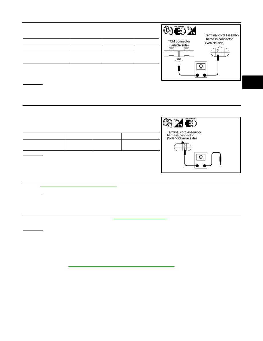
3.
Check continuity between terminal cord assembly harness con-
nector terminal and TCM connector terminal.
4.
If OK, check harness for short to ground and short to power.
5.
If OK, check continuity between ground and transaxle assembly.
6.
Reinstall any part removed.
OK or NG
OK
>> GO TO 4.
NG
>> Repair open circuit or short to ground or short to power in harness or connectors.
4.
CHECK VALVE RESISTANCE
1.
Turn ignition switch OFF.
2.
Disconnect terminal cord assembly connector in engine room.
3.
Check resistance between terminal cord assembly harness con-
nector terminal and ground.
OK or NG
OK
>> GO TO 5.
NG
>> Repair or replace damaged parts.
5.
CHECK DTC
Perform
TM-93, "DTC Confirmation Procedure"
.
OK or NG
OK
>> INSPECTION END
NG
>> GO TO 6.
6.
CHECK TCM
1.
Check TCM input/output signal. Refer to
.
2.
If NG, recheck TCM pin terminals for damage or loose connection with harness connector.
OK or NG
OK
>> INSPECTION END
NG
>> Repair or replace damaged parts.
Component Inspection
INFOID:0000000001694385
OVERRUN CLUTCH SOLENOID VALVE
• For removal, refer to
TM-191, "Control Valve Assembly and Accumulators"
.
Resistance Check
Item
Connector
Terminal
Continuity
TCM
E101
20
Yes
Terminal cord assembly
harness connector
F30
3
SCIA3260E
Solenoid valve
Connector
Terminal
Resistance (Approx.)
Overrun clutch solenoid
valve
F30
3 - Ground
20 - 30
Ω
SCIA3455E