содержание .. 1228 1229 1230 1231 ..
Nissan Tiida C11. Manual - part 1230
STR-6
< FUNCTION DIAGNOSIS >
[HR16DE]
STARTING SYSTEM
FUNCTION DIAGNOSIS
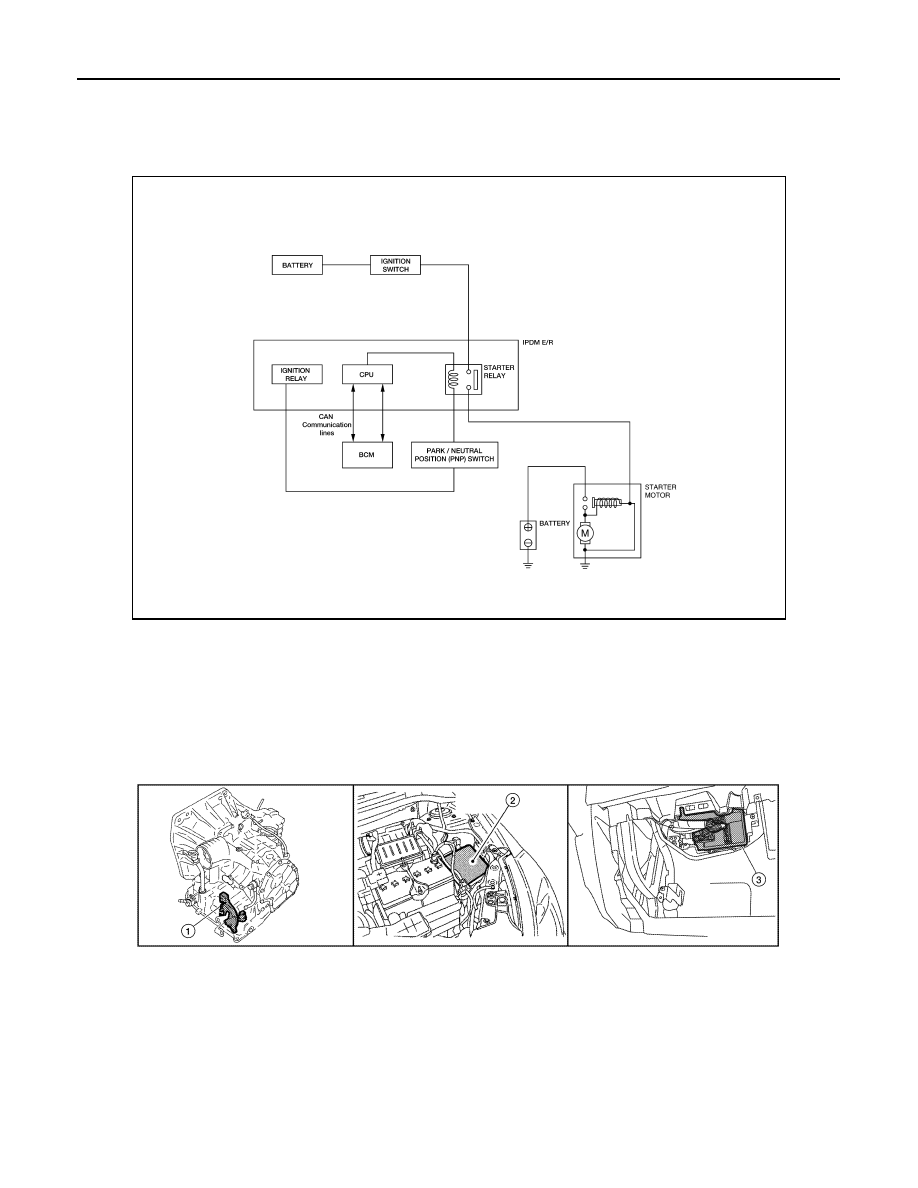
STARTING SYSTEM
System Diagram
INFOID:0000000001712878
System Description
INFOID:0000000001712879
The starter motor plunger closes and provides a closed circuit between the battery and the starter motor. The
starter motor is grounded to the cylinder block. With power and ground supplied, the starter motor operates.
Component Parts Location
INFOID:0000000001712880
ALBIA0472GB
1.
Park/Neutral position (PNP) switch
F25
2.
IPDM E/R E44, E45, E46
3.
BCM M18 (view with glove box re-
moved)
ALBIA0474GB