Nissan Tiida C11. Manual - part 1222


  Главная      Nissan     Nissan Tiida C11 - Service Manual


поиск по сайту            


содержание   ..  1220  1221  1222  1223   ..


Nissan Tiida C11. Manual - part 1222


C1604 TORQUE SENSOR

STC-11

< COMPONENT DIAGNOSIS >

[EPS]

C

D

E

F

H

I

J

K

L

M

A

B

STC

N

O

P

C1604 TORQUE SENSOR

Description

INFOID:0000000001716736

Torque sensor detects the steering torque, and transmit the signal to EPS control unit.

DTC Logic

INFOID:0000000001716737

DTC DETECTION LOGIC

DTC CONFIRMATION PROCEDURE

1.

CHECK SELF-DIAGNOSIS RESULTS

Check the self-diagnosis results.

Is above displayed on the self-diagnosis display?

YES

>> Proceed to diagnosis procedure. Refer to 

STC-11, "Diagnosis Procedure"

.

NO

>> INSPECTION END

Diagnosis Procedure

INFOID:0000000001697725

1.

CHECK TORQUE SENSOR SIGNAL

With CONSULT-III

1.

Start engine.

2.

Select “DATA MONITOR“ mode for “EPS” with CONSULT-III.

3.

Check the value of “TORQUE SENSOR”. Refer to 

STC-22, "EPS Control Unit Input/Output Signal Refer-

ence Value"

.

Without CONSULT-III

1.

Start engine.

2.

Check voltage between EPS control unit harness connector M53 terminals 4, 5, 6, 7 and ground. Refer to

STC-22, "EPS Control Unit Input/Output Signal Reference Value"

.

OK or NG

OK

>> GO TO 3.

NG

>> GO TO 2.

2.

CHECK HARNESS AND CONNECTOR

1.

Turn ignition switch OFF.

2.

Disconnect EPS control unit harness connector and torque sensor harness connector.

3.

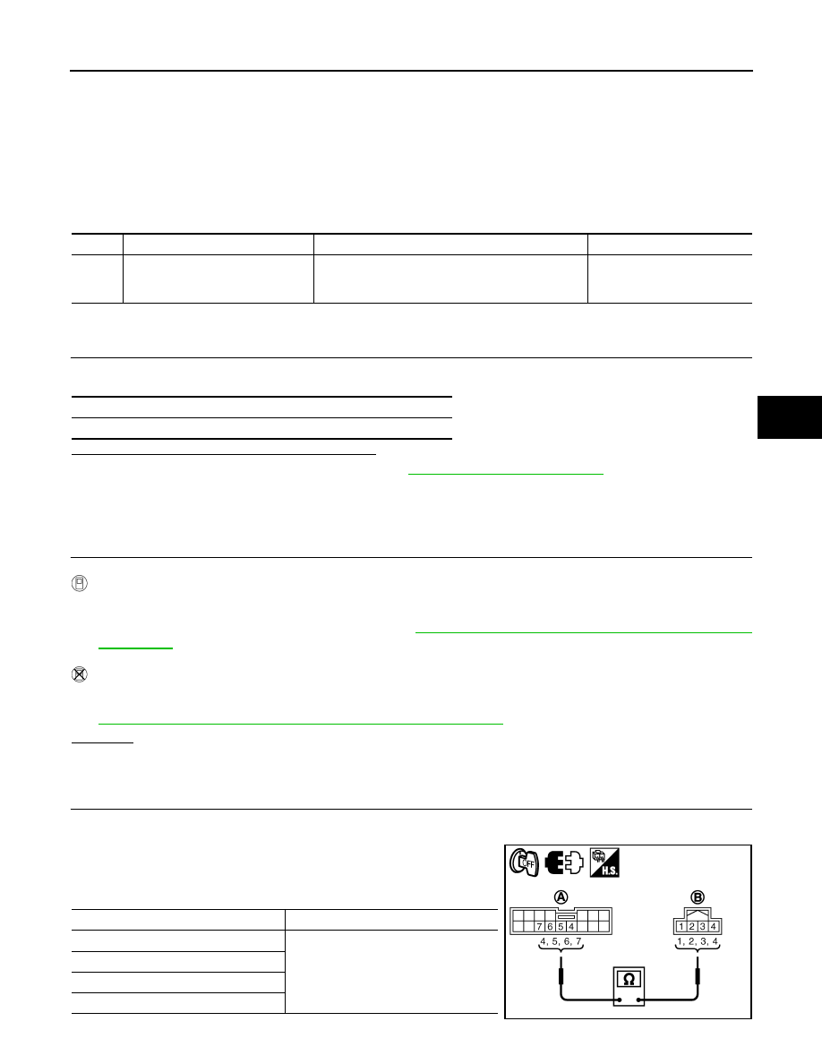
Check continuity between EPS control unit harness connector
M53 (A) terminals 4, 5, 6, 7 and torque sensor harness connec-
tor M63 (B) terminals 1, 2, 3, 4.

DTC

Display item

Malfunction detected condition

Possible cause

C1604

TORQUE SENSOR

Malfunction of the torque sensor in steering column 
assembly is detected.

• Harness or connector
• Torque sensor
• EPS control unit

Self-diagnosis results

TORQUE SENSOR

Terminal

Continuity

4 – 3

Yes

5 – 2

6 – 1

7 – 4

SGIA1629E

STC-12

< COMPONENT DIAGNOSIS >

[EPS]

C1604 TORQUE SENSOR

Also check harness for short to ground and short to power.

4.

Connect EPS control unit harness connector and torque sensor harness connector.

OK or NG

OK

>> GO TO 3.

NG

>> Repair or replace damaged parts.

3.

CHECK EPS CONTROL UNIT

Check EPS control unit input/output signal. Refer to 

STC-22, "EPS Control Unit Input/Output Signal Reference

Value"

.

OK or NG

OK

>> GO TO 4.

NG

>> Check EPS control unit pin terminals for damage or loose connection with harness connector. If

any items are damaged, repair or replace damaged parts.

4.

CHECK DTC

Perform the self-diagnosis, after driving the vehicle for a while.
OK or NG

OK

>> INSPECTION END

NG

>> Torque sensor is malfunctioning. Replace steering column assembly. Refer to 

ST-9, "Removal

and Installation"

.

Special Repair Requirement (Models with ESP)

INFOID:0000000001730964

1.

ADJUSTMENT OF STEERING ANGLE SENSOR NEUTRAL POSITION

Always perform the neutral position adjustment for the steering angle sensor, when replacing the EPS control
unit. Refer to 

BRC-90, "ADJUSTMENT OF STEERING ANGLE SENSOR NEUTRAL POSITION : Descrip-

tion"

.

>> END

C1606 EPS MOTOR

STC-13

< COMPONENT DIAGNOSIS >

[EPS]

C

D

E

F

H

I

J

K

L

M

A

B

STC

N

O

P

C1606 EPS MOTOR

Description

INFOID:0000000001716739

EPS motor provides the assist torque by control signal from EPS control unit.

DTC Logic

INFOID:0000000001716740

DTC DETECTION LOGIC

DTC CONFIRMATION PROCEDURE

1.

CHECK SELF-DIAGNOSIS RESULTS

Check the self-diagnosis results.

Is above displayed on the self-diagnosis display?

YES

>> Proceed to diagnosis procedure. Refer to 

STC-13, "Diagnosis Procedure"

.

NO

>> INSPECTION END

Diagnosis Procedure

INFOID:0000000001697726

1.

CHECK EPS MOTOR SIGNAL

With CONSULT-III

1.

Start engine.

2.

Select “DATA MONITOR” mode for “EPS” with CONSULT-III.

3.

Check the values of “MOTOR SIG” and “MOTOR CURRENT”. Refer to 

STC-22, "EPS Control Unit Input/

Output Signal Reference Value"

.

OK or NG

OK

>> GO TO 3.

NG

>> GO TO 2.

2.

CHECK EPS MOTOR

1.

Turn ignition switch OFF.

2.

Disconnect EPS control unit harness connector.

3.

Check resistance between EPS control unit harness connector
terminals.

4.

Connect EPS control unit harness connector.

OK or NG

OK

>> GO TO 3.

NG

>> EPS motor is malfunctioning. Replace steering column

assembly. Refer to 

ST-9, "Removal and Installation"

.

3.

CHECK EPS CONTROL UNIT

Check EPS control unit input/output signal. Refer to 

STC-22, "EPS Control Unit Input/Output Signal Reference

Value"

.

DTC

Display item

Malfunction detected condition

Possible cause

C1606

EPS MOTOR

When the motor driver malfunction of EPS control 
unit or EPS motor malfunction is detected.

• Harness or connector
• EPS motor
• EPS control unit

Self-diagnosis results

EPS MOTOR

Connector

Terminal

Resistance

M60

19 – 20

Approx. 0.1 

 or less

AWGIA0030ZZ

STC-14

< COMPONENT DIAGNOSIS >

[EPS]

C1606 EPS MOTOR

OK or NG

OK

>> GO TO 4.

NG

>> Check EPS control unit pin terminals for damage or loose connection with harness connector. If

any items are damaged, repair or replace damaged parts.

4.

CHECK DTC

Perform the self-diagnosis, after driving the vehicle for a while.

OK or NG

OK

>> INSPECTION END

NG

>> GO TO 3.

Special Repair Requirement (Models with ESP)

INFOID:0000000001730965

1.

ADJUSTMENT OF STEERING ANGLE SENSOR NEUTRAL POSITION

Always perform the neutral position adjustment for the steering angle sensor, when replacing the EPS control
unit. Refer to 

BRC-90, "ADJUSTMENT OF STEERING ANGLE SENSOR NEUTRAL POSITION : Descrip-

tion"

.

>> END


содержание   ..  1220  1221  1222  1223   ..