Nissan Tiida C11. Manual - part 1195


  Главная      Nissan     Nissan Tiida C11 - Service Manual


поиск по сайту            


содержание   ..  1193  1194  1195  1196   ..


Nissan Tiida C11. Manual - part 1195


SRC-8

< FUNCTION DIAGNOSIS >

SRS AIR BAG SYSTEM

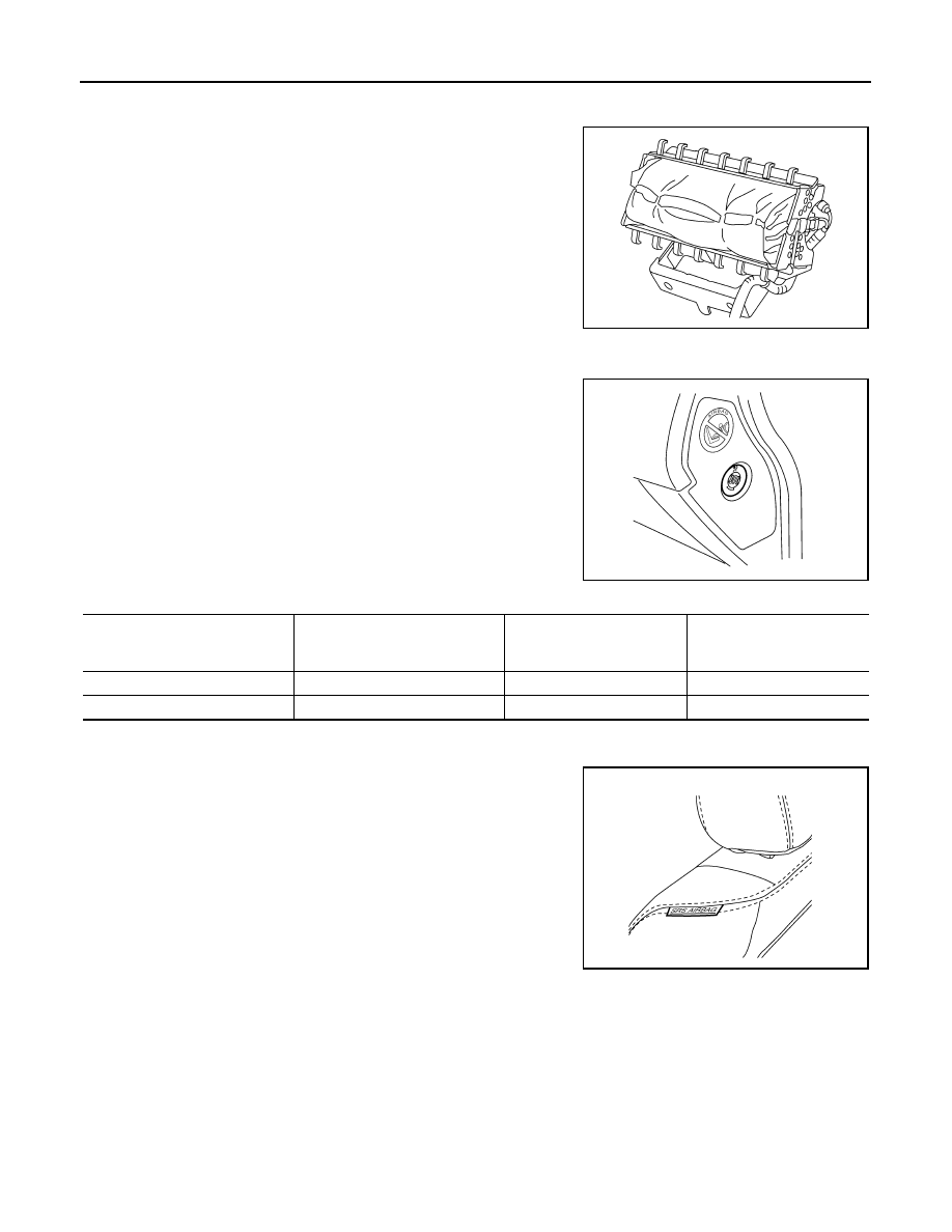
Front Passenger Air Bag Module

INFOID:0000000001396422

The front passenger air bag module is single stage and located
behind the instrument panel assembly (mounted to the steering
member).  It operates with the SRS system in a frontal collision
exceeding a specified level.

Passenger Air Bag Deactivation Switch

INFOID:0000000001404302

The passenger air bag deactivation switch is located on the RH side
of the instrument panel.  The switch can be operated with the ignition
key (models without Intelligent Key) or mechanical key (models with
Intelligent Key).  When the switch is turned to th ON positition, the
passenger air bag is enabled and could inflate in a frontal collision.
When the switch is turned to the OFF position, the passenger air bag
is disabled and will not inflate in a frontal collision.  After any SRS
repair, make sure the passenger air bag deactivation switch is in the
same position as when the vehicle arrived for service.
NOTE:
In case of customer concern, CONSULT-III can be used to confirm
the passenger air bag status (readiness).

Passenger Air Bag Deactivation Switch Status

Front Side Air Bag

INFOID:0000000001396351

Front side air bag modules are built into the front seatback assem-
blies.  Vehicles with side air bags are equipped with labels as shown.

Side Curtain Air Bag

INFOID:0000000001396352

Side curtain air bag modules are located above the vehicle headlining.

WHIA0326E

AWHIA0003ZZ

Passenger Air Bag Deactivation 

Switch

(Position)

PASS AIR BAG OFF Indicator

Passenger Air Bag Status

(Readiness)

CONSULT-III Display

ON

OFF

Active (enabled)

ON

OFF

ON

Deactivated (disabled)

OFF

WHIA0327E

SRS AIR BAG SYSTEM

SRC-9

< FUNCTION DIAGNOSIS >

C

D

E

F

G

I

J

K

L

M

A

B

SRC

N

O

P

Vehicles with side curtain air bags are equipped with labels as
shown.

Seat Belt Warning Lamp Control Unit

INFOID:0000000001724663

The seat belt warning lamp control unit is located under the passen-
ger seat.  The control unit monitors the status of the driver and pas-
senger seat belt buckle switches as well as vehicle speed.  The
control unit uses a timer to turn the driver and passenger seat belt
warning lamps ON and OFF.

Seat Belt Pre-tensioners

INFOID:0000000001396423

The front seat belt pre-tensioners are installed for both the driver's
seat and the front passenger's seat. They operate simultaneously
with the SRS air bag system in the event of a frontal collision with an
impact exceeding a specified level.
The lap seat belt pre-tensioner (2), mounted in the belt anchor posi-
tion, works in conjuction with the front LH or RH seat belt pre-ten-
sioner (1) depending on drive configuration (LHD/RHD).
When the frontal collision with an impact exceeding a specified level
occurs, seat belt slack resulting from clothing or other factors is
immediately taken up by the pre-tensioners. Vehicle passengers are
securely restrained.
When passengers in a vehicle are thrown forward in a collision and
the restraining force of the seat belt exceeds a specified level, the load limiter permits the specified extension
of the seat belt by the twisting of the ELR shaft, and a relaxation of the chest-area seat belt web tension while
maintaining force.

Direct-connect SRS Component Connectors

INFOID:0000000001396354

The following SRS components use direct-connect style harness connectors.
• Driver air bag module
• Front passenger air bag module
• LH side curtain air bag module
• RH side curtain air bag module
• Front LH seat belt pre-tensioner
• Lap seat belt pre-tensioner
• Front RH seat belt pre-tensioner
Always pull up to release locking tab prior to removing connector from SRS component.

WHIA0041E

ALHIA0090ZZ

WHIA0340E

SRC-10

< FUNCTION DIAGNOSIS >

SRS AIR BAG SYSTEM

Always push down to lock locking tab after installing connector to
SRS component. When locked, the locking tab is level with the con-
nector housing.

WHIA0103E

ON BOARD DIAGNOSTIC (OBD) SYSTEM

SRC-11

< FUNCTION DIAGNOSIS >

C

D

E

F

G

I

J

K

L

M

A

B

SRC

N

O

P

ON BOARD DIAGNOSTIC (OBD) SYSTEM

Trouble Diagnosis Introduction

INFOID:0000000001396360

CAUTION:

• Do not use electrical test equipment on any circuit related to the SRS unless instructed to do so in

this Service Manual. SRS wiring harnesses can be identified by yellow and/or orange harness con-
nectors.

• Do not attempt to repair, splice or modify SRS wiring harnesses. If a harness is damaged, replace it

with a new one.

• Keep ground connections clean.

DIAGNOSIS FUNCTION

The SRS self-diagnosis results can be read by using “AIR BAG” warning lamp and/or CONSULT-III. 
The User mode is exclusively prepared for the customer (driver). This mode warns the driver of a system mal-
function through the operation of the “AIR BAG” warning lamp.
The Diagnosis mode allows the technician to locate and inspect the malfunctioning part.
The mode applications for the “AIR BAG” warning lamp and CONSULT-III are as follows:

HOW TO PERFORM TROUBLE DIAGNOSES FOR QUICK AND ACCURATE REPAIR

A good understanding of the malfunction conditions can make troubleshooting faster and more accurate.
In general, each customer feels differently about a malfunction. It is important to fully understand the symp-
toms or conditions for a customer complaint.

Information From Customer

WHAT - Vehicle model
WHEN - Date, Frequencies
WHERE - Road conditions
HOW - Operating conditions, Symptoms

Preliminary Check

Check that the following parts are in good order.
• Battery
• Fuses
• System component-to-harness connections

SRS Operation Check

INFOID:0000000001396361

DIAGNOSTIC PROCEDURE 1

Checking SRS Operation Using “AIR BAG” Warning Lamp—User Mode

1.

Turn the ignition switch from OFF to ON, and check that the air bag warning lamp blinks.

2.

Compare the SRS air bag warning lamp blinking pattern with the
examples.

User mode

Diagnosis mode

Display type

“AIR BAG” warning lamp

X

X

ON-OFF operation

CONSULT-III

X

Monitoring

BF-1845D


содержание   ..  1193  1194  1195  1196   ..