Nissan Tiida C11. Manual - part 1100


  Главная      Nissan     Nissan Tiida C11 - Service Manual


поиск по сайту            


содержание   ..  1098  1099  1100  1101   ..


Nissan Tiida C11. Manual - part 1100


MWI-90

< SYMPTOM DIAGNOSIS >

THE OIL PRESSURE WARNING LAMP DOES NOT TURN OFF

THE OIL PRESSURE WARNING LAMP DOES NOT TURN OFF

Description

INFOID:0000000001538679

The oil pressure warning lamp remains illuminated while the engine is running (normal oil pressure).

Diagnosis Procedure

INFOID:0000000001538680

1.

CHECK OIL PRESSURE WARNING LAMP

Perform auto active test. Refer to 

PCS-10, "Diagnosis Description"

.

Is oil pressure warning lamp illuminated?

YES

>> GO TO 2

NO

>> Replace combination meter. Refer to 

MWI-94, "Removal and Installation"

.

2.

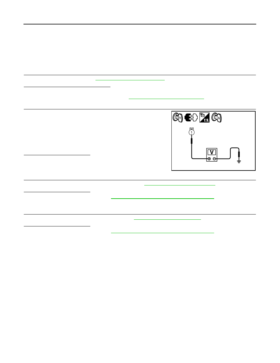
CHECK IPDM E/R OUTPUT VOLTAGE

1.

Turn ignition switch OFF.

2.

Disconnect the oil pressure switch connector.

3.

Turn ignition switch ON. 

4.

Check voltage between the oil pressure switch harness connec-
tor F32 terminal 1 and ground.

Is the inspection result normal?

YES

>> GO TO 3

NO

>> GO TO 4

3.

CHECK OIL PRESSURE SWITCH

Perform a unit check for the oil pressure switch. Refer to 

MWI-31, "Component Inspection"

.

Is the inspection result normal?

YES

>> Replace IPDM E/R. Refer to 

PCS-30, "Removal and Installation of IPDM E/R"

.

NO

>> Replace oil pressure switch.

4.

CHECK OIL PRESSURE SWITCH SIGNAL CIRCUIT

check the oil pressure switch signal circuit. Refer to 

MWI-31, "Diagnosis Procedure"

.

Is the inspection result normal?

YES

>> Replace IPDM E/R. Refer to 

PCS-30, "Removal and Installation of IPDM E/R"

.

NO

>> Repair harness or connector.

1 – Ground

: Approx. 12V

PKIC1144E

MWI

THE AMBIENT TEMPERATURE DISPLAY IS INCORRECT

MWI-91

< SYMPTOM DIAGNOSIS >

C

D

E

F

G

H

I

J

K

L

M

B

A

O

P

THE AMBIENT TEMPERATURE DISPLAY IS INCORRECT

Description

INFOID:0000000001538673

• The displayed ambient air temperature is higher than the actual temperature.
• The displayed ambient air temperature is lower than the actual temperature.

Diagnosis Procedure

INFOID:0000000001538674

NOTE:
Check that the symptom is not applicable to the normal operating condition before starting diagnosis. Refer to

MWI-17, "INFORMATION DISPLAY : System Description"

.

1.

CHECK AMBIENT SENSOR SIGNAL CIRCUIT

Check the ambient sensor signal circuit. Refer to 

MWI-34, "Diagnosis Procedure"

.

Is the inspection result normal?

YES

>> GO TO 2

NO

>> Repair harness or connector.

2.

CHECK AMBIENT SENSOR UNIT

Perform a unit check for the ambient sensor. Refer to 

HAC-131, "Ambient Sensor Component Inspection"

(without NAVI) or 

HAC-245, "Ambient Sensor Component Inspection"

 (with NAVI).

Is the inspection result normal?

YES

>> Replace combination meter. Refer to 

MWI-94, "Removal and Installation"

.

NO

>> Replace ambient sensor.

MWI-92

< SYMPTOM DIAGNOSIS >

NORMAL OPERATING CONDITION

NORMAL OPERATING CONDITION

INFORMATION DISPLAY

INFORMATION DISPLAY : Description

INFOID:0000000001538681

OUTSIDE AIR TEMPERATURE

The displayed outside air temperature on the information display may differ from the actual temperature
because it is a corrected value calculated from the ambient sensor signal by the combination meter. Refer to

MWI-17, "INFORMATION DISPLAY : System Description"

 for details on the correction process.

MWI

PRECAUTIONS

MWI-93

< PRECAUTION >

C

D

E

F

G

H

I

J

K

L

M

B

A

O

P

PRECAUTION

PRECAUTIONS

Supplemental Restraint System (SRS) "AIR BAG" and "SEAT BELT PRE-TENSION-
ER"

INFOID:0000000001374731

The Supplemental Restraint System such as “AIR BAG” and “SEAT BELT PRE-TENSIONER”, used along
with a front seat belt, helps to reduce the risk or severity of injury to the driver and front passenger for certain
types of collision. Information necessary to service the system safely is included in the SR and SB section of
this Service Manual.

WARNING:

• To avoid rendering the SRS inoperative, which could increase the risk of personal injury or death in

the event of a collision which would result in air bag inflation, all maintenance must be performed by
an authorized NISSAN/INFINITI dealer.

• Improper maintenance, including incorrect removal and installation of the SRS, can lead to personal

injury caused by unintentional activation of the system. For removal of Spiral Cable and Air Bag
Module, see the SR section.

• Do not use electrical test equipment on any circuit related to the SRS unless instructed to in this

Service Manual. SRS wiring harnesses can be identified by yellow and/or orange harnesses or har-
ness connectors.


содержание   ..  1098  1099  1100  1101   ..