Nissan Tiida C11. Manual - part 69


  Главная      Nissan     Nissan Tiida C11 - Service Manual


поиск по сайту            


содержание   ..  67  68  69  70   ..


Nissan Tiida C11. Manual - part 69


BRC-42

< COMPONENT DIAGNOSIS >

[ABS]

C1115 WHEEL SENSOR

Check for inflation pressure, wear and size of each tire.

Are tire pressure and size correct and is tire wear within specifications?

YES

>> GO TO 4

NO

>> Adjust tire pressure or replace tire(s).

4.

CHECK WHEEL BEARINGS

Check wheel bearing axial end play. Refer to 

FAX-6, "On-Vehicle Inspection and Service"

 (front) or 

RAX-5,

"On-Vehicle Inspection and Service"

 (rear).

Is the inspection result normal?

YES

>> GO TO 5

NO

>> Repair or replace as necessary. Refer to 

FAX-7, "Removal and Installation"

 (front) or 

RAX-6,

"Removal and Installation"

 (rear).

5.

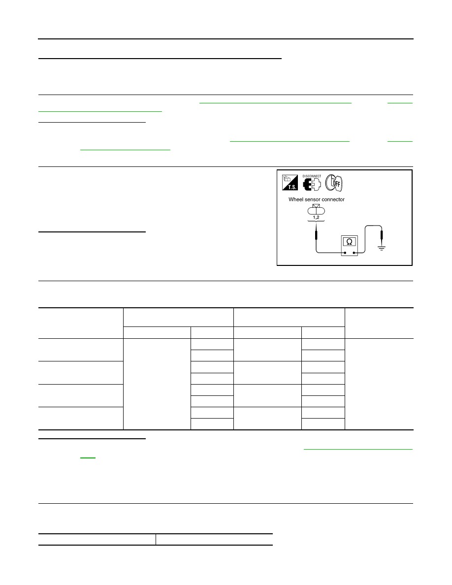
CHECK WIRING HARNESS FOR SHORT CIRCUIT

1.

Disconnect ABS actuator and electric unit (control unit) connec-
tor and wheel sensor connector of malfunction code No.

2.

Check continuity between wheel sensor harness connector ter-
minals and ground.

Is the inspection result normal?

YES

>> GO TO 6

NO

>> Repair the circuit.

6.

CHECK WIRING HARNESS FOR OPEN CIRCUIT

1.

Check continuity between ABS actuator and electric unit (control unit) harness connector E125 and the
malfunctioning wheel sensor harness connector E18, E117, C10, or C11.

Is the inspection result normal?

YES

>> Replace the ABS actuator and electric unit (control unit). Refer to 

BRC-85, "Removal and Installa-

tion"

.

NO

>> Repair the circuit.

Component Inspection

INFOID:0000000001731255

1.

CHECK DATA MONITOR

On “DATA MONITOR”, select “FR LH SENSOR”, “FR RH SENSOR”, “RR LH SENSOR”, and “RR RH SEN-
SOR”, and check the vehicle speed.

Continuity should not exist.

WFIA0343E

Wheel sensor

ABS actuator and 

electric unit (control unit)

Wheel sensor

Continuity

Connector

Terminal

Connector

Terminal

Front LH

E125

45

E18

1

Yes

46

2

Front RH

34

E117

1

33

2

Rear LH

37

C11

2

36

1

Rear RH

42

C10

2

43

1

Wheel sensor

Vehicle speed (DATA MONITOR)

C1115 WHEEL SENSOR

BRC-43

< COMPONENT DIAGNOSIS >

[ABS]

C

D

E

G

H

I

J

K

L

M

A

B

BRC

N

O

P

Is the inspection result normal?

YES

>> INSPECTION END

NO

>> Go to diagnosis procedure. Refer to 

BRC-41, "Diagnosis Procedure"

.

Special Repair Requirement

INFOID:0000000001731256

1.

ADJUSTMENT OF STEERING ANGLE SENSOR NEUTRAL POSITION

Always perform neutral position adjustment for the steering angle sensor when replacing the ABS actuator
and electric unit (control unit). Refer to 

BRC-90, "ADJUSTMENT OF STEERING ANGLE SENSOR NEUTRAL

POSITION : Description"

.

>> GO TO 2

2.

CALIBRATION OF DECEL G SENSOR

Always perform calibration of decel G sensor when replacing the ABS actuator and electric unit (control unit).
Refer to 

BRC-91, "CALIBRATION OF DECEL G SENSOR : Description"

.

>> END

FR LH SENSOR

Nearly matches the speedometer dis-
play (

±

10% or less)

FR RH SENSOR

RR LH SENSOR

RR RH SENSOR

BRC-44

< COMPONENT DIAGNOSIS >

[ABS]

C1116 STOP LAMP SWITCH

C1116 STOP LAMP SWITCH

Description

INFOID:0000000001731257

The stop lamp switch transmits the stop lamp switch signal (ON/OFF) to the ABS actuator and electric unit
(control unit). 

DTC Logic

INFOID:0000000001731258

DTC DETECTION LOGIC

DTC CONFIRMATION PROCEDURE

1.

CHECK SELF-DIAGNOSIS RESULTS

Check the self-diagnosis results.

Is above displayed on the self-diagnosis display?

YES

>> Proceed to diagnosis procedure. Refer to 

BRC-44, "Diagnosis Procedure"

.

NO

>> INSPECTION END

Diagnosis Procedure

INFOID:0000000001731259

INSPECTION PROCEDURE

1.

CONNECTOR INSPECTION

1.

Disconnect the ABS actuator and electric unit (control unit) connector E125 and stop lamp switch connec-
tor E38. 

2.

Check the terminals for deformation, disconnection, looseness or damage.

Is the inspection result normal?

YES

>> GO TO 2

NO

>> Repair or replace as necessary.

2.

STOP LAMP SWITCH INSPECTION

Check the voltage between the ABS actuator and electric unit (con-
trol unit) harness connector E125 terminal 41 and body ground.

Is the inspection result normal?

YES

>> Perform self-diagnosis again. If the same results

appear, replace ABS actuator and electric unit (control
unit). Refer to 

BRC-85, "Removal and Installation"

.

NO

>> GO TO 3

3.

STOP LAMP RELAY CIRCUIT INSPECTION

DTC

Display item

Malfunction detected condition

Possible cause

C1116

STOP LAMP SW

When stop lamp switch circuit is open.

• Harness or connector
• Stop lamp switch
• ABS actuator and electric unit 

(control unit)

Self-diagnosis results

STOP LAMP SW

Brake pedal depressed

: Battery voltage 
(approx. 12V)

Brake pedal not depressed

: Approx. 0V

AWFIA0019ZZ

C1116 STOP LAMP SWITCH

BRC-45

< COMPONENT DIAGNOSIS >

[ABS]

C

D

E

G

H

I

J

K

L

M

A

B

BRC

N

O

P

1.

Disconnect the stop lamp relay harness connector E12.

2.

Check the continuity between the ABS actuator and electric unit
(control unit) harness connector E125 (B) terminal 41 and stop
lamp relay harness connector E12 (A) terminal 4.

Is the inspection result normal?

YES

>> Refer to 

BRC-6, "Work Flow"

.

NO

>> Repair or replace malfunctioning components.

Special Repair Requirement

INFOID:0000000001731260

1.

ADJUSTMENT OF STEERING ANGLE SENSOR NEUTRAL POSITION

Always perform neutral position adjustment for the steering angle sensor when replacing the ABS actuator
and electric unit (control unit). Refer to 

BRC-90, "ADJUSTMENT OF STEERING ANGLE SENSOR NEUTRAL

POSITION : Description"

.

>> GO TO 2

2.

CALIBRATION OF DECEL G SENSOR

Always perform calibration of decel G sensor when replacing the ABS actuator and electric unit (control unit).
Refer to 

BRC-91, "CALIBRATION OF DECEL G SENSOR : Description"

.

>> END

Continuity should exist.

AWFIA0020ZZ


содержание   ..  67  68  69  70   ..