Главная Nissan Nissan Tiida C11 - Service Manual
поиск по сайту
содержание .. 45 46 47 48 ..
Nissan Tiida C11. Manual - part 47
BCS-52
< ECU DIAGNOSIS >
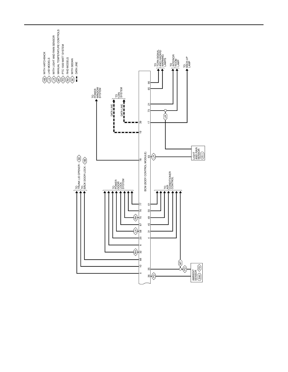
BCM (BODY CONTROL MODULE)
ALMWA0069GB