Nissan Tiida C11. Manual - part 4


  Главная      Nissan     Nissan Tiida C11 - Service Manual


поиск по сайту            


содержание   ..  1  2  3  4  5  ..


Nissan Tiida C11. Manual - part 4


AV-10

< COMPONENT DIAGNOSIS >

[AUDIO WITHOUT NAVIGATION]

POWER SUPPLY AND GROUND CIRCUIT

2.

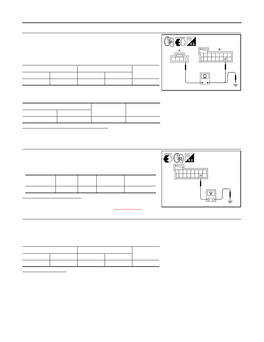
CHECK POWER SUPPLY CIRCUIT (CONTINUITY)

1.

Turn ignition switch OFF.

2.

Disconnect microphone and AV control unit harness connectors.

3.

Check continuity between microphone harness connector R15
(A) terminal 4 and AV control unit harness connector M44 (B)
terminal 29. 

4.

Check continuity between microphone harness connector R15
(A) terminal 4 and ground. 

Are the continuity test results as specified?

YES

>> GO TO 3

NO

>> Repair harness or connector.

3.

CHECK POWER SUPPLY CIRCUIT (AV CONTROL UNIT SIDE)

1.

Connect AV control unit harness connector.

2.

Turn ignition switch to ACC.

3.

Check voltage between AV control unit harness connector M44
terminal 29 and ground.

Is approximately 5V present?

YES

>> Inspection End.

NO

>> Replace AV control unit. Refer to 

XX-XX, "*****"

4.

CHECK GROUND CIRCUIT

1.

Turn ignition switch OFF.

2.

Disconnect microphone harness connector R15 and AV control unit harness connector M44.

3.

Check continuity between microphone harness connector R15 (A) terminal 2 and AV control unit harness
connector M44 (B) terminal 28. 

Does continuity exist?

YES

>> Inspection End.

NO

>> Repair harness or connector.

A

B

Continuity

Connector

Terminal

Connector

Terminal

R15

4

M44

29

Yes

A

Continuity

Connector

Terminal

R15

4

Ground

No

ALNIA0320GB

Signal name

Connector 

No.

Terminal 

No.

Ignition switch 

position

Value (Approx.)

MIC power

M44

29

ACC

5V

ALNIA0321GB

A

B

Continuity

Connector

Terminal

Connector

Terminal

R15

2

M44

28

Yes

AV

STEERING SWITCH

AV-11

< COMPONENT DIAGNOSIS >

[AUDIO WITHOUT NAVIGATION]

C

D

E

F

G

H

I

J

K

L

M

B

A

O

P

STEERING SWITCH

Description

INFOID:0000000001728773

When one of the steering wheel AV control switches is pushed, the resistance in the steering wheel AV control
switch circuit changes depending on which button is pushed.

Diagnosis Procedure

INFOID:0000000001728774

1.

CHECK STEERING WHEEL AUDIO CONTROL SWITCH RESISTANCE

1.

Disconnect steering wheel audio control switch connector M102.

2.

Check resistance between steering switch connector terminals.

Do the steering wheel audio control switches check OK?

YES

>> GO TO 2

NO

>> Replace steering wheel audio control switch. Refer to 

XX-XX, "*****"

.

2.

CHECK HARNESS

1.

Turn ignition switch OFF.

2.

Disconnect AV control unit connector M43 and spiral cable con-
nector M30.

3.

Check continuity between AV control unit harness connector
M43 (A) and spiral cable harness connector M30 (B).

4.

Check continuity between AV control unit connector M43 (A) and ground.

Are the continuity results as specified?

YES

>> GO TO 3

NO

>> Repair harness.

3.

SPIRAL CABLE CHECK

Terminal

Signal name

Condition

Resistance 

(

)

(Approx.)

16

17

Seek (down)

Depress  

switch.

165

Volume (down)

Depress VOL down switch.

487

Power

Depress PWR switch.

0

20

17

Seek (up)

Depress  

switch.

165

Volume (up)

Depress VOL up switch.

487

Mode

Depress MODE switch.

0

WKIA4457E

A

Continuity

Connector

Terminal

Connector

Terminal

M43

6

M30

24

Yes

15

31

16

32

A

Continuity

Connector

Terminal

M43

6

Ground

No

15

16

ALNIA0332GB

AV-12

< COMPONENT DIAGNOSIS >

[AUDIO WITHOUT NAVIGATION]

STEERING SWITCH

1.

Disconnect spiral cable connector M102.

2.

Check continuity between spiral cable harness connector M30
(A) and M102 (B).

Does the spiral cable check OK?

YES

>> Inspection End.

NO

>> Replace spiral cable. Refer to 

XX-XX, "*****"

.

Spiral cable

Continuity

Connector

Terminal

Connector

Terminal

M30

24

M102

20

Yes

31

17

32

16

ALNIA0333GB

AV

MICROPHONE SIGNAL CIRCUIT

AV-13

< COMPONENT DIAGNOSIS >

[AUDIO WITHOUT NAVIGATION]

C

D

E

F

G

H

I

J

K

L

M

B

A

O

P

MICROPHONE SIGNAL CIRCUIT

Description

INFOID:0000000001728771

Voice signals are transmitted from the microphone to the AV control unit using the microphone signal circuits.

Diagnosis Procedure

INFOID:0000000001728772

1.

CHECK HARNESS BETWEEN AV CONTROL UNIT AND MICROPHONE

1.

Turn ignition switch OFF.

2.

Disconnect AV control unit connector and microphone connector.

3.

Check continuity between AV control unit harness connector M44 and microphone harness connector
R15.

4.

Check continuity between AV control unit harness connector M44 and ground.

Are the continuity test results as specified?

YES

>> GO TO 2

NO

>> Repair harness or connector.

2.

CHECK MICROPHONE POWER SUPPLY

1.

Connect AV control unit connector and microphone connector.

2.

Turn ignition switch ON.

3.

Check voltage between microphone harness connector R15 ter-
minal 4 and ground.

Is voltage reading approx. 5 volts?

YES

>> GO TO 3

NO

>> Replace AV control unit. Refer to 

XX-XX, "*****"

.

3.

CHECK MICROPHONE SIGNAL

Check signal between AV control unit harness connector M44 terminals 27 and 28 with CONSULT-III or and
oscilliscope.

Terminal

Terminal

Continuity

Connector

Terminal

Connector

Terminal

M44

27

R15

1

Yes

28

2

29

4

Terminal

Continuity

Connector

Terminal

M44

7

Ground

No

8

29

4 - Ground

: Approx. 5V

WKIA5796E


содержание   ..  1  2  3  4  5  ..