Mitsubishi Eclipse Cross (2023 year). Manual in english - page 16
Automatic air conditioning (if so equipped)
NOTE
z If the “
” indicator light is on, you cannot
turn the air conditioning off or select the
recirculation position. This prevents the win-
dows from fogging up.
z To defog quickly, direct the air flow from the
side vents toward the door windows.
z When defrosting, do not set the temperature
to the maximum cool position. This will
blow cool air on the window glass and fog it
up.
7
7-14
Comfort controls

Dual-zone automatic climate control air conditioning (if so equipped)
Dual-zone automatic climate control air conditioning (if so equipped)
N00731501483
The air conditioning can only be used while the engine is running.
Control panel
N00711801855
7
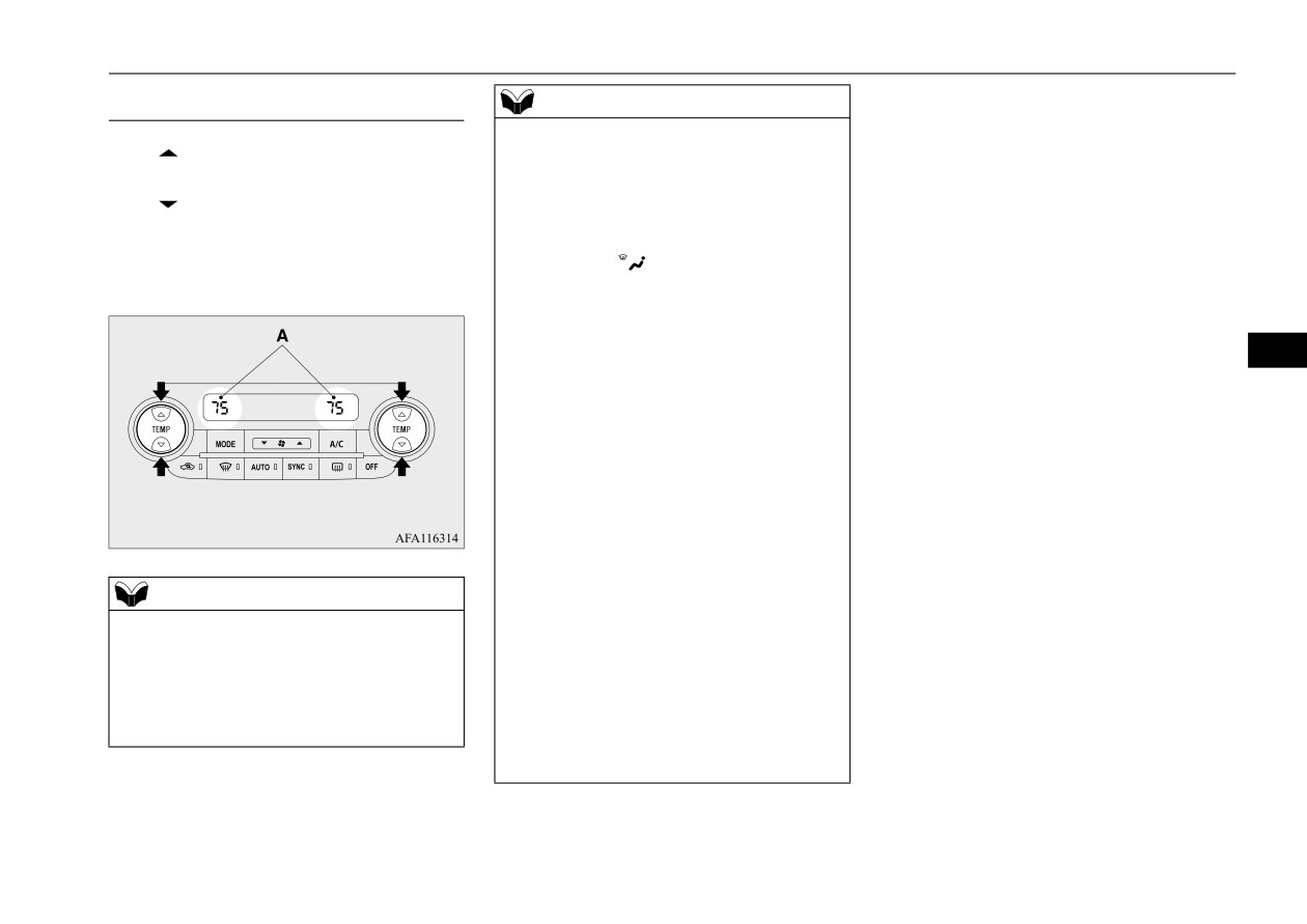
1- Driver’s side temperature control
7- Defogger switch P.7-18
14- Air conditioning indicator P.7-20
switch P.7-17
8- AUTO switch P.7-21
15- Blower speed display P.7-16
2- MODE switch P.7-18
9- SYNC switch P.7-17
16- Passenger’s side temperature display
3- Blower speed selection switch
10- Electric rear window defogger switch
P.7-17
P.7-16
P.5-211
4- Air conditioning switch P.7-20
11- OFF switch P.7-21
5- Passenger’s side temperature control
12- Driver’s side temperature display
switch P.7-17
P.7-17
6- Air selection switch P.7-19
13- Mode selection display P.7-18
Comfort controls
7-15

Dual-zone automatic climate control air conditioning (if so equipped)
NOTE
Blower speed selection switch
NOTE
z
There is an interior air temperature sensor
N00736901336
z
Due to a drop in the battery voltage or some
(A) in the illustrated position.
other problem, the blower speed may tempo-
Press
of the blower speed selection
Never place anything over the sensor, since
rarily become less than the selected blower
switch to increase the blower speed.
doing so will prevent it from functioning
speed display setting or the fan may stop.
properly.
Press
of the blower speed selection
If the fan stops, set the operation mode to
switch to decrease the blower speed.
OFF, wait a few minutes, and then set the
The selected blower speed (A) will be shown
operation mode back to ON.
in the display.
In the following cases, have the system
inspected by your authorized Mitsubishi
Motors dealer or a repair facility of your
choice.
7
• The blower speed remains lower than the
blower speed set using the blower speed
display or the blower speed decreases fre-
z
Since the air conditioning operation is con-
quently.
trolled while the ECO mode is operating,
• The fan does not operate even after stop-
you may feel that effectiveness of the air
ping and restarting the engine or the fan
conditioning is insufficient.
stops frequently.
Refer to “ECO mode switch” on page 5-204.
z
Even during ECO mode operation, you can
select normal operation of the air condition-
1-
Increase
ing.
2-
Decrease
On vehicles equipped with the Smartphone-
link Display Audio
(SDA) or the Smart-
phone-link Display Audio (SDA) navigation
system, screen operations can be used to
change the setting. Refer to the separate
owner’s manual for details.
z
In extreme cold, the air conditioning control
panel screen may operate sluggishly. This
does not indicate a problem.
It will disappear when the vehicle interior
temperature rises to a normal temperature.
7-16
Comfort controls
Dual-zone automatic climate control air conditioning (if so equipped)
air conditioning switch to match your per-
Temperature control switch
NOTE
sonal preferences.
N00737001523
z
When the engine coolant temperature is low,
Contact your authorized Mitsubishi Motors
Press
of the temperature control switch to
the air temperature from the heater will be
dealer or a repair facility of your choice for
increase the temperature.
cool/cold until the engine warms up, even if
assistance.
you have selected warm air with the switch.
Press
of the temperature control switch to
Refer to “Personalizing the air conditioning
To prevent the windshield and windows
decrease the temperature.
switch (Changing the function setting)” on
from fogging up, the vent mode will be
The selected temperature (A) will be shown
page 7-20.
changed to “
” and the blower speed will
in the display.
be reduced while the system is operating in
Refer to
“Personalizing the air selection
the AUTO mode.
(Changing the function setting)” on page
z
When you feel that it is hotter or colder than
7-19.
the set temperature, you may adjust it to your
7
preference.
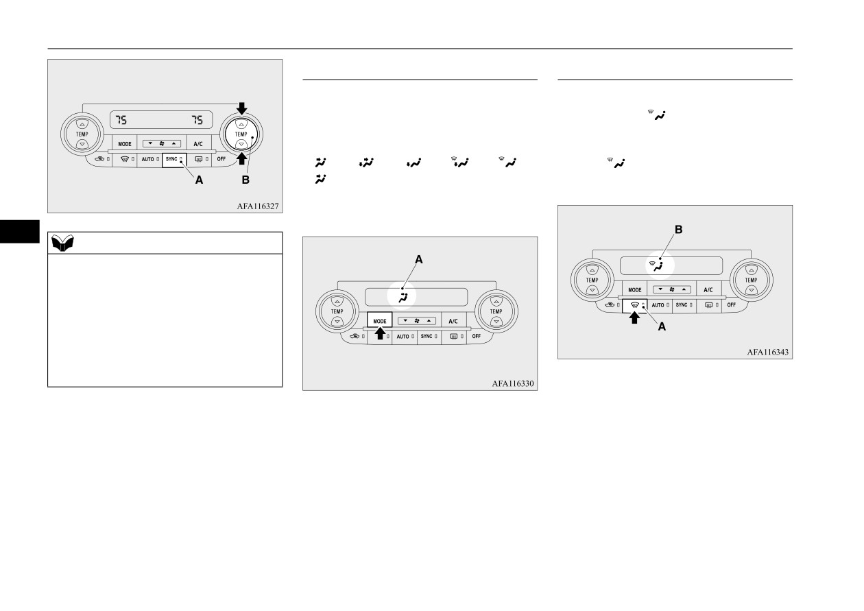
To control the driver’s side and the
For further information, we recommend you
passenger’s side temperature inde-
consult an authorized Mitsubishi Motors
dealer or a repair facility of your choice.
pendently
z
When the temperature is set to the highest or
the lowest setting, the air selection and the
When the indicator light
(A) goes off by
air conditioning will be automatically
pressing the passenger’s side temperature
changed as follows.
control switch (B) or the SYNC switch, the
Also, if the air selection is operated manually
driver’s side and the passenger’s side temper-
after an automatic changeover, manual oper-
ature can be controlled independently of each
ation will be selected.
NOTE
other.
• Quick Heating (When the temperature is set
z
The temperature value of air conditioning is
to the highest setting)
switched in conjunction with outside temper-
Outside air will be introduced and the air
ature display unit of the multi-information
conditioning will stop.
display.
• Quick Cooling (When the temperature is set
Refer to “Changing the temperature unit” on
to the lowest setting)
page 5-158.
Inside air will be recirculated and the air
conditioning will operate.
The above indicates the factory settings. You
can personalize the air selection switch and
Comfort controls
7-17
Dual-zone automatic climate control air conditioning (if so equipped)
MODE switch
Defogger switch
N00737101292
N00703401100
To change the amount of air flowing from the
When this switch is pressed, the mode
vents, press the MODE switch. Each time the
changes to the “
” mode and the blower
MODE switch is pressed, the mode changes
speed will be set at the maximum automati-
to the next one in the following sequence:
cally. The indicator light (A) will come on
“
” “
” “
” “
” “
”
and the “
” mode is shown in the display
“
”. The selected mode is shown in the dis-
(B).
play (A). Refer to “Changing the mode selec-
tion” on page 7-3.
7
NOTE
z
When the indicator light (A) comes on by
pressing the SYNC switch, the passenger’s
side temperature will be controlled to the
same setting temperature as the driver’s side.
When the indicator light (A) illuminates, if
the driver’s side temperature control switch
is pressed, the passenger’s side setting tem-
perature will be synchronized to the driver’s
side.
7-18
Comfort controls
Dual-zone automatic climate control air conditioning (if so equipped)
NOTE
NOTE
z
When the defogger switch is pressed, the air
z When the engine coolant temperature rises to
conditioning system automatically operates
a certain level, the air selection is automati-
and outside air (as opposed to recirculated
cally switched to the recirculation position
air) is selected. This automatic switching
and the indicator light (A) comes on. At this
control is carried out to prevent misting of
time, the system will not switch to the out-
the windows even if “Disable automatic air
side position even if the air selection switch
conditioning control” or “Disable automatic
is pushed.
air selection control” is set. Refer to “Person-
alizing the air conditioning switch (Changing
Personalizing the air selection
the function setting)” on page 7-20, “Person-
(Changing the function setting)
alizing the air selection (Changing the func-
When the air conditioning turns on, the air
N00712300111
7
tion setting)” on page 7-19.
selection is controlled automatically. When
You can change the following functions to
z The indicator light
(A) will go off when
adjusting the blower speed.
the air conditioning turns off, the air selection
match your preference.
automatically goes back to the outside posi-
tion.
z
Enable automatic air selection control:
If high cooling performance is desired, or if
When the AUTO switch is pressed, the air
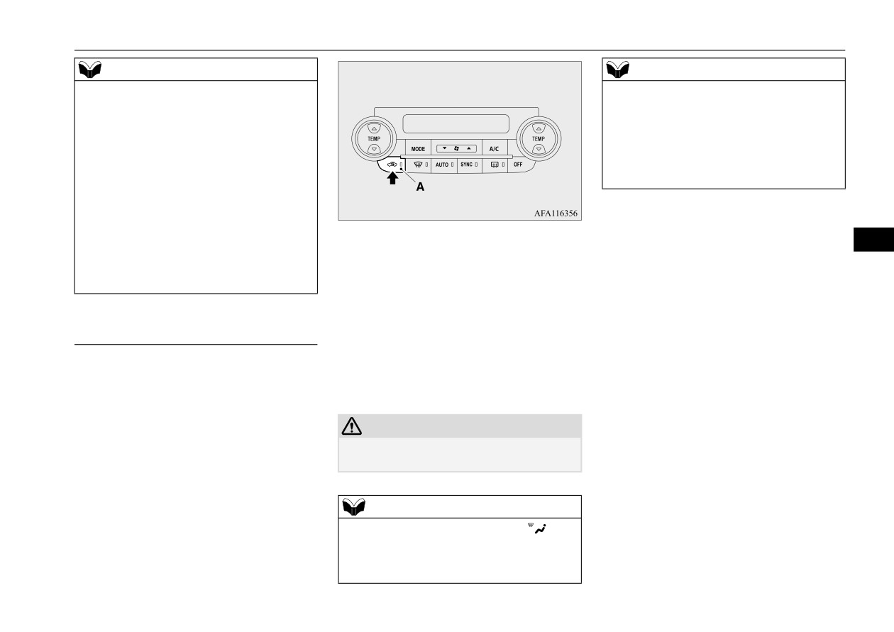
Air selection switch
the outside air is dusty or contaminated in
selection switch will also be automatically
N00737201482
some way, use the recirculation position.
controlled.
Normally, use the outside air position to keep
Switch to the outside position every now and
the windshield and side windows clear and to
z
Disable automatic air selection control:
then to keep the windows from fogging up.
quickly remove fog or frost from the wind-
Even when the AUTO switch is pressed,
shield.
the air selection switch will not be auto-
CAUTION
matically controlled.
To change the air selection, simply press the
z Using recirculated air for a long time may
air selection switch.
cause the windows to fog up.
z Changing the settings:
Press the air selection switch for approxi-
z Outside air {Indicator light (A) OFF}
mately 10 seconds or longer.
Outside air is introduced into the passen-
NOTE
When the setting has changed, the system
ger compartment.
z If the mode selection is set to the “
” posi-
will beep and the indicator light will flash.
z Recirculated air {Indicator light (A) ON}
tion, you cannot turn the air conditioning off
Air is recirculated inside the passenger
or select the recirculation position.
compartment.
This prevents the windows from fogging up.
Comfort controls
7-19

Dual-zone automatic climate control air conditioning (if so equipped)
• When the setting has changed from
Personalizing the air conditioning
enabled to disabled, the system will beep
switch (Changing the function set-
three times and the indicator light will
ting)
flash three times.
N00712200136
• When the setting has changed from dis-
You can change the following functions to
abled to enabled, the system will beep
match your preference.
two times and the indicator light will
flash three times.
z
Enable automatic air conditioning control:
On vehicles equipped with the Smart-
When the AUTO switch is pressed, or
phone-link Display Audio (SDA) or the
when the temperature control switch has
Smartphone-link Display Audio (SDA)
been set to the minimum temperature, the
7
navigation system, screen operations can
Push the switch again and the air condition-
air conditioning switch is automatically
also be used to change the setting. Refer
ing compressor will stop and the indicator
controlled.
to the separate owner’s manual for
goes off.
details.
z
Disable automatic air conditioning con-
trol:
NOTE
The air conditioning switch is not auto-
NOTE
z
If a problem is detected in the air condition-
matically controlled, unless the air condi-
z
The factory setting is “Enable automatic air
ing compressor, the “
” indicator blinks.
tioning switch is used.
selection control”.
Press the air conditioning switch once to turn
z
When the defogger switch is pressed, the air
it off, then once more to turn it back on. If
z
Changing the settings:
selection will automatically change to the
the“
” indicator does not blink, there is
Press the air conditioning switch for
outside air position, even if the system is set
no problem. If it does blink, have it checked
approximately 10 seconds or longer.
to “Disable automatic air selection control”,
at an authorized Mitsubishi Motors dealer or
in order to prevent windows from fogging
When the setting has changed, the system
a repair facility of your choice.
up.
will beep and the indicator light will flash.
z
For example, sometimes after using a high-
• When the setting has changed from
pressure car wash, the condenser can get wet,
enabled to disabled, the system will beep
and the “
” indicator blinks temporarily.
Air conditioning switch
three times and the indicator light will
Wait for a while, press the air conditioning
N00737301483
flash three times.
switch once to turn the system off, then once
• When the setting has changed from dis-
Push the switch, and the air conditioning
more to turn it back on. Once the water evap-
orates, the blinking will stop.
abled to enabled, the system will beep
compressor will turn on. The “
” indicator
two times and the indicator light will
(A) will be shown in the display.
flash three times.
7-20
Comfort controls

Dual-zone automatic climate control air conditioning (if so equipped)
On vehicles equipped with the Smart-
OFF switch
phone-link Display Audio (SDA) or the
N00703601056
Smartphone-link Display Audio (SDA)
Push the switch to turn off the air condition-
navigation system, screen operations can
ing system.
also be used to change the setting. Refer
to the separate owner’s manual for
details.
NOTE
z The factory setting is “Enable automatic air
conditioning control”.
7
z When the defogger switch is pressed, the air
conditioning will run automatically, even if
the system is set to “Disable automatic air
conditioning control”, in order to prevent
windows from fogging up.
AUTO switch
N00703501084
When the AUTO switch is pressed, the indi-
cator light (A) comes on and the mode selec-
tion, blower speed adjustment, recirculated/
outside air selection, temperature adjustment,
and air conditioning ON/OFF status are all
controlled automatically. The selected mode
and the blower speed are not shown in the
display.
Comfort controls
7-21

Dual-zone automatic climate control air conditioning (if so equipped)
Operating the air conditioning
NOTE
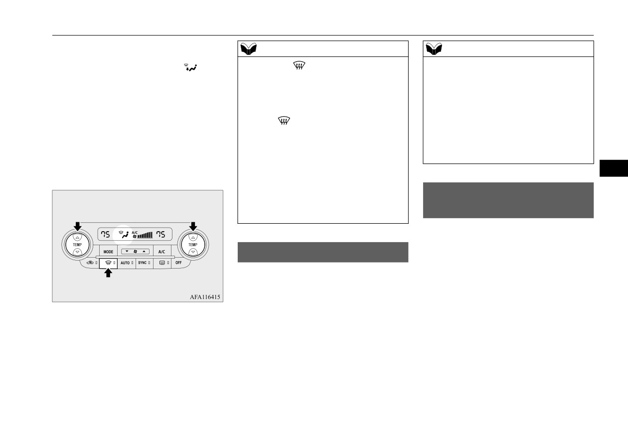
Defrosting or defogging (wind-
system (automatic mode)
z
Set the temperature at approximately
75
shield, door windows)
(when the outside temperature unit of the
N00732401636
N00731701616
multi-information display shows °F) or 24
(when the outside temperature unit of the
CAUTION
multi-information display shows °C) under
z For safety, make sure you have a clear view
normal conditions.
through all the windows.
z
When the engine coolant temperature is low,
the air temperature from the heater will be
To remove frost or mist from the windshield
cool/cold until the engine warms up, even if
and door windows, use the MODE switch or
you have selected warm air with the temper-
ature switch. To prevent the windshield and
defogger switch (“
” or “
”).
7
windows from fogging up, the vent mode
will be changed to “
” and the blower
For ordinary defrosting
speed will be reduced.
In normal conditions, use the system in the
Use this setting to keep the windshield and
AUTO mode and follow these procedures:
door windows clear of mist, and to keep the
Operating the air conditioning
leg area
heated
(when
driving
in
rain
or
1. Push the AUTO switch.
system (manual mode)
snow).
2. Set the temperature control switch to the
N00731801125
desired temperature. The temperature can
Blower speed and vent mode may be con-
be set within a range of around 61 (LO) to
trolled manually by setting the blower speed
89 (HI) (when the outside temperature
selection switch and the MODE switch to the
unit of the multi-information display
desired positions. To return to automatic
shows °F) or 17 (LO) to 31 (HI) (when the
operation, press the AUTO switch.
outside temperature unit of the multi-
information display shows °C).
The vents, recirculated/outside air, blower
speed, temperature adjustment, and ON/OFF
of the air conditioning will be controlled
automatically.
7-22
Comfort controls
Air purifier
1. Set the air selection switch to the outside
NOTE
NOTE
position.
z Operation in certain conditions such as driv-
2. Set the MODE switch to the “
” posi-
z
While the “
” indicator light is on, the air
ing on a dusty road and frequent use of the
conditioning compressor will run automati-
tion.
air conditioning can lead to reduction of ser-
cally. The outside air position will also be
3. Select your desired blower speed by
vice life of the filter. When you feel that the
selected and the blower speed will be set at
pressing the blower speed selection
air flow is lower than normal or when the
the maximum automatically.
switch.
windshield or windows start to fog up easily,
z
If the “
” indicator light is on, you cannot
4. Select your desired temperature by press-
replace the air filter.
turn the air conditioning off or select the
ing the temperature control switch.
Contact your authorized Mitsubishi Motors
recirculation position. This prevents the win-
5. Push the air conditioning switch.
dealer or a repair facility of your choice for
dows from fogging up.
assistance.
z
To defog quickly, direct the air flow from the
7
For quick defrosting
side vents toward the door windows.
z
When defrosting, do not set the temperature
to the maximum cool position. This will
General information about
blow cool air on the window glass and fog it
your radio
up.
N00733901566
Your vehicle’s radio receives both AM and
FM stations.
Air purifier
The quality of your reception is affected by
N00733801220
distance, obstacles, and signal interference.
The air conditioning system is equipped with
an air filter to remove pollen and dust.
This radio complies with Part 15 of Federal
The air filter’s ability to collect pollen and
Communications Commission (FCC) Rules
dirt is reduced as it becomes dirty, so replace
(for vehicles sold in U.S.A.). Operation is
1. Push the defogger switch.
it periodically. For the maintenance interval,
subject to the following conditions:
2. Set the temperature to the highest posi-
refer to the “WARRANTY AND MAINTE-
tion.
z The device may not cause harmful inter-
NANCE MANUAL”.
ference.
z This device must accept any interference
recieved, including interference that may
cause undesirable operation.
Comfort controls
7-23
General information about your radio
CAUTION
Weak reception (fading)
z Changes or modifications not expressly
approved by the party meeting the above
Because of the limited range of FM signals
conditions could void the user’s authority to
and the way FM waves transmit, you may
operate the equipment.
experience weak or fading FM reception.
When the broadcast is blocked by mountains
or similar obstructions, reception can be dis-
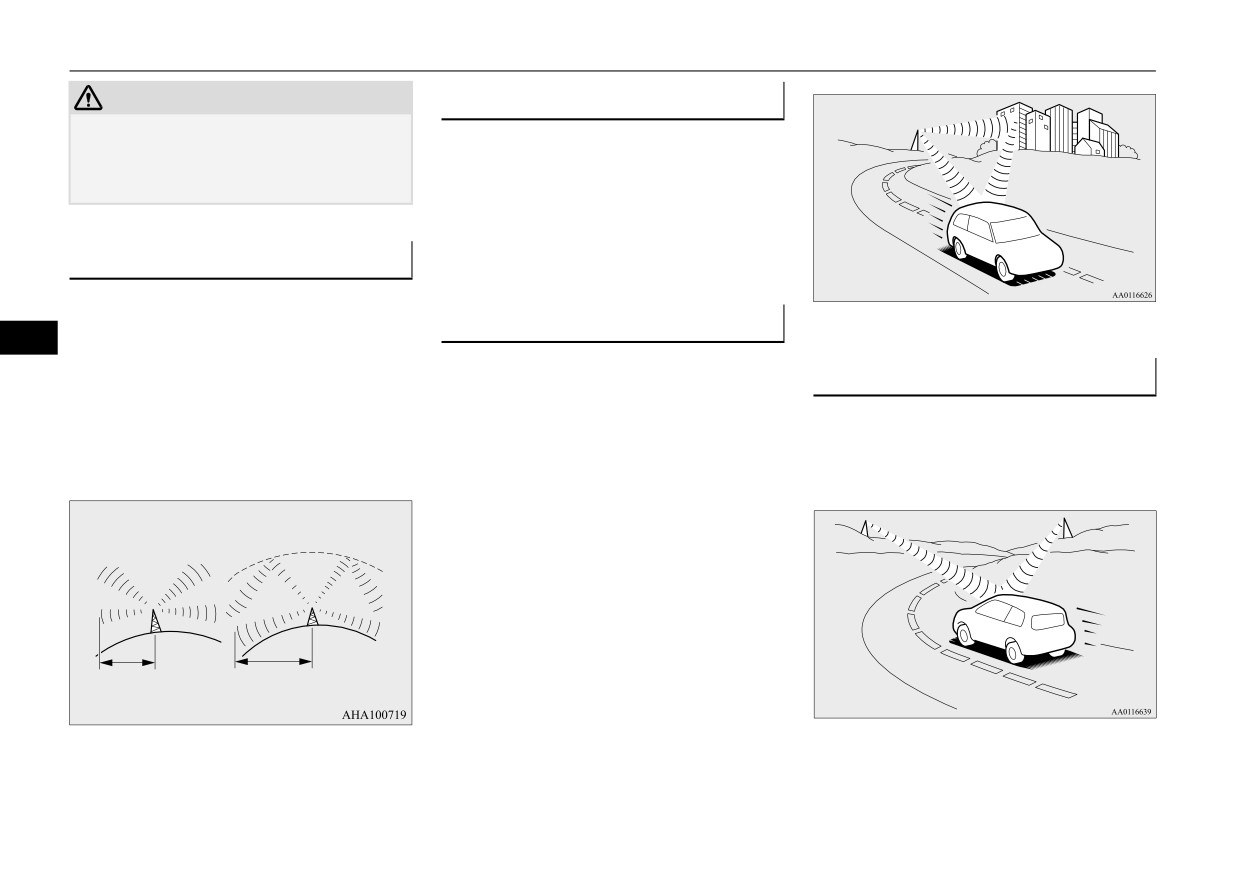
Signal transmission
turbed.
FM signals do not follow the earth surface
nor are they reflected by the upper atmo-
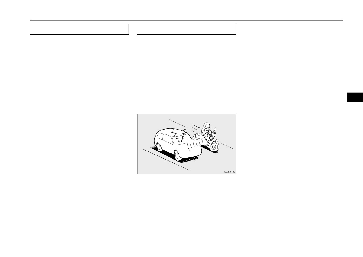
Reflection
7
sphere. For this reason, FM broadcasts cannot
be received over long distances. AM signals
The reason why one can hear FM but not AM
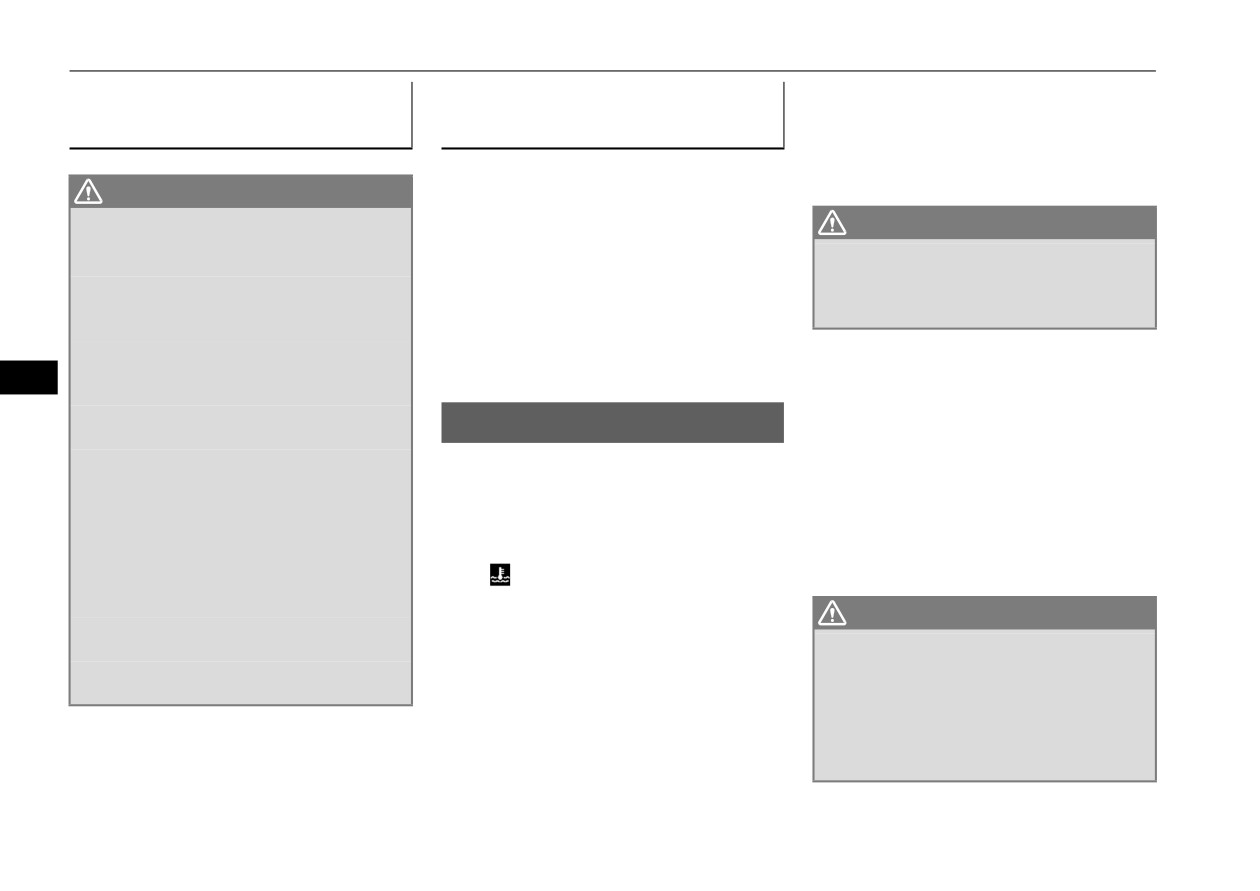
Cross modulation
follow the earth’s surface and are reflected by
in parking garages, under bridges etc., is that
the upper atmosphere. For this reason, AM
FM signals, unlike AM signals, are reflected
If one listens to a weak station and is in the
broadcasts can be received over longer dis-
by solid objects such as buildings, etc.
vicinity of another strong station, both sta-
tances.
Because FM signals are easily reflected by
tions might be received simultaneously.
buildings, this can also cause reception dis-
turbances.
FM
AM
The direct signal from the broadcast station
reaches the antenna slightly before the
reflected signal. This time difference may
cause some reception disturbance or flutter.
This problem occurs primarily in urban areas.
25 to 40 mile radius
100 mile radius
(40 to 64 km)
(160 km)
7-24
Comfort controls
General information about your radio
FM stereo reception
Causes of disturbances
FM reception is affected by the electrical sys-
Stereo reception requires a high quality
tems of vehicles in the vicinity, especially
broadcast signal. This means that types of
those without an electronic noise suppression
disturbances mentioned previously become
device. The disturbance is even greater if the
more marked and the reception range is
station is weak or poorly tuned.
somewhat diminished during stereo recep-
FM reception is not as sensitive to electrical
tion.
disturbances as AM. AM reception is sensi-
tive to electrical disturbances such as power
lines, lightning and other types of similar
7
electrical phenomena.
Comfort controls
7-25
For emergencies
If the vehicle breaks down
8-2
If the operation mode cannot be changed to OFF
(vehicles equipped with the F.A.S.T.-key)
8-2
Jump-starting the engine
8-2
Engine overheating
8-4
Jack and tools
8-5
How to change a tire
8-6
Towing
8-11
8
Operation under adverse driving conditions
8-12
Fuel Pump Shut-off System
8-13

If the vehicle breaks down
If the vehicle breaks down
If the operation mode can-
WARNING
N00836301230
z To reduce the risk of igniting flammable
not be changed to OFF
gas that may be emitted from the battery,
If your vehicle breaks down on the road,
(vehicles equipped with the
carefully read this section before jump-
move to the shoulder and turn on the hazard
starting the vehicle.
warning flashers. If there is no shoulder, or
F.A.S.T.-key)
z Do not try to start your vehicle by pushing
the shoulder is not safe, drive in the right lane
N00860700087
or towing. This can cause an accident
slowly with the hazard lights flashing, until
If the operation mode cannot be changed to
resulting in serious injury or death and
you come to a safe stopping place. Keep the
OFF, perform the following procedure.
can damage the vehicle.
flashers flashing.
1. Move the selector lever to the
“P”
(PARK) position, and then change the
NOTE
If the engine stops/fails
operation mode to OFF.
z Do not use jumper cables if they have dam-
8
2. One of the other causes could be low bat-
age or corrosion.
If the engine stops, there will be no power
tery voltage. If this occurs, the keyless
assist to the steering and brakes, making these
entry system and the F.A.S.T.-key opera-
1. Take off any metal jewelry such as watch
difficult to use.
tion will also not operate. Contact an
bands or bracelets that might create an
authorized Mitsubishi Motors dealer or a
z The brake booster will not work, so the
accidental electrical contact.
repair facility of your choice.
brakes will not grip well. The brake pedal
2. Position the vehicles close enough
will be harder to press than usual.
together so that the jumper cables can
z Since there is no power steering assist, the
Jump-starting the engine
reach, but be sure the vehicles aren’t
steering wheel will be hard to turn.
N00836401879
touching each other.
If the engine cannot be started because the
CAUTION
When the engine fails at the
battery is weak or dead, you can start it with
z Check the other vehicle. It must have a 12-
the battery from another vehicle using jumper
intersection
volt battery. If the other system isn’t 12-volt,
cables.
both systems can be damaged.
Get help from your passengers, bystanders,
etc. to push the vehicle and move it to a safe
3. Set the parking brake firmly on your vehi-
area.
cle and move the selector lever into the
“P” (PARK) position.
8-2
For emergencies
Jump-starting the engine
4. Set the parking brake firmly on the other
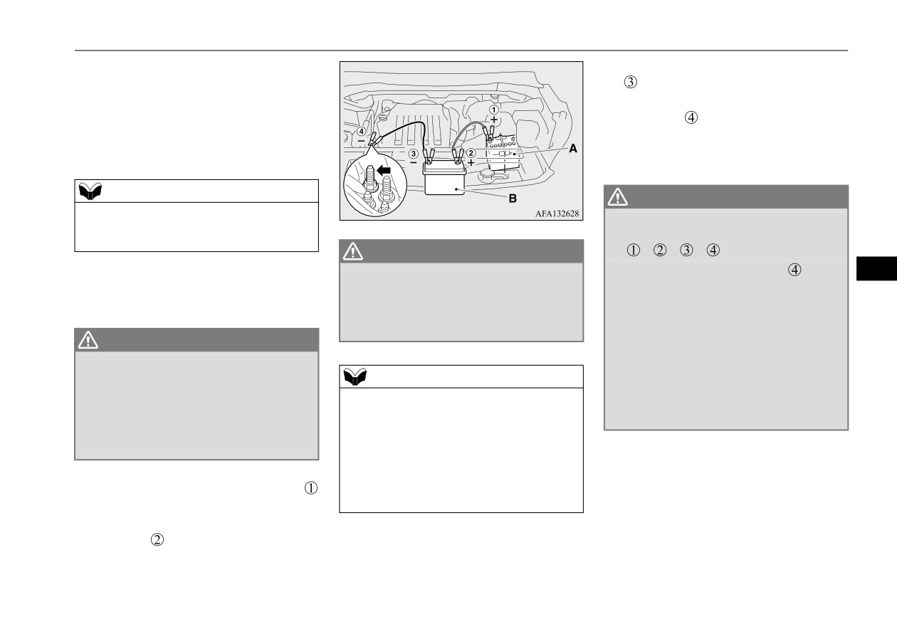
8. Connect one end of the other jumper cable
vehicle. Put the automatic transaxle in “P”
to the negative
(-) terminal of the
(PARK) or the manual transaxle in “N”
booster battery (B), and then connect the
(Neutral).
other end
to the designated ground
5. Turn the ignition switch
(the engine
location of the vehicle with the discharged
switch) on each vehicle to the “LOCK” or
battery (A) at the point farthest from the
“OFF” position.
battery.
NOTE
WARNING
z Turn off all lights, heater, and other electrical
z
Be sure to follow the proper order when
loads. This will avoid sparks and help save
connecting
the
batteries,
of:
both batteries.
WARNING
z
Make sure that the jumper cables and
z
Make sure that the connection
is made
8
6. Make sure your battery electrolyte is at
your clothing are clear of the cooling fans
to the correct designated location
(as
the proper level. Refer to “Battery” on
and drive belts. Entanglement with the
shown in the illustration) properly. If the
page 9-10.
fans or belts can cause serious personal
connection is directly made to the negative
injury.
(-) terminal of the battery, the flammable
WARNING
gases from inside the battery might catch
z If the electrolyte fluid is not visible, or
fire and explode, causing personal injury.
looks frozen, DO NOT ATTEMPT JUMP
z
When connecting the jumper cable, do not
NOTE
STARTING!!
connect the positive (+) cable to the nega-
z
Open the terminal cover before connecting
The battery might split open or explode if
tive (-) terminal. Sparks can make the bat-
the jumper cable to the positive terminal of
the temperature is below the freezing
tery explode.
the battery.
point or if it is not filled to the proper
Refer to “Battery” on page 9-10.
level.
z
Use the proper cables suitable for the battery
9. Start the engine in the vehicle providing
size.
the boost. Let the engine idle a few min-
7. Connect one end of one jumper cable
Otherwise heat damage to the cables could
utes, then start the engine in the vehicle
to the positive
(+) terminal of the dis-
result.
with the discharged battery.
charged battery (A), and then connect the
10. After the engine is started, disconnect the
other end
to the positive (+) terminal
cables in the reverse order from the way
of the booster battery (B).
you connected them.
For emergencies
8-3
Engine overheating
3. Check that the cooling fan is running. If
Charging the battery by using
As your vehicle has anti-lock
the fan is not turning, stop the engine
an external battery charger
brakes
immediately and contact an authorized
Mitsubishi Motors dealer or a repair facil-
If you drive your vehicle with a low battery
ity of your choice for assistance.
WARNING
charge after the engine has been started by
z
Always remove the battery from your
using jumper cables, the engine may misfire.
WARNING
vehicle when the battery is charged by an
This can cause the anti-lock braking system
z To avoid personal injury, keep hands,
external battery charger.
warning light to blink on and off. This is only
hair, jewelry and clothes away from the
z
Keep sparks, cigarettes, and flames away
due to the low battery voltage. It is not a
cooling fan. The cooling fan can start at
from the battery because the battery could
any time.
problem with the brake system. If this hap-
explode.
pens, fully charge the battery and ensure the
z
Keep your work area well vented when
charging or using the battery in an
charging system is operating properly.
4. If you see steam or spray coming from
8
enclosed space.
under the hood, turn off the engine.
z
Remove all the caps before charging the
5. If you do not see steam or spray coming
Engine overheating
battery.
from under the hood, leave the engine on
N00836501421
z
Electrolyte (battery acid) is made of corro-
until the high coolant temperature warn-
sive diluted sulfuric acid. If electrolyte
When the engine is overheating, the informa-
ing goes off. After the high coolant tem-
comes in contact with your hands, eyes,
tion screen in the multi-information display
perature warning has gone off, you can
clothes, or the painted surface of your
will be interrupted and the engine coolant
start driving again. If the high coolant
vehicle, thoroughly flush with water. If
temperature warning display will appear.
temperature warning stays on, turn off the
electrolyte gets in your eyes, flush them
Also “
” will blink.
engine.
immediately and thoroughly with water,
and get prompt medical attention.
If these warnings are displayed:
WARNING
z
Always wear protective clothing and gog-
1. Stop the vehicle in a safe place. Turn on
z Before raising the engine hood, check to
gles when working near the battery.
the hazard warning flashers.
see if there is steam or spray coming from
z
Keep the battery out of the reach of chil-
2. With the engine still running, carefully
under the hood. Steam or spray coming
dren.
raise the engine hood to vent the engine
from an overheated engine could seriously
scald you.
compartment.
Do not open the hood until there is no
steam or spray.
8-4
For emergencies

Jack and tools
6. When you do not see any more steam or
10. Replace the radiator cap and tighten it
Tools
spray, open the hood. Look for obvious
fully. Check the engine coolant tempera-
leaks, such as a split radiator hose. Be
ture display on the multi-information dis-
careful as components will be hot. Any
play. You can start driving again when the
leak source must be repaired.
high coolant temperature warning does
7. If there is no obvious leak source, check
not come on.
the coolant level in the engine coolant
11. Have the system inspected by your autho-
reserve tank. If there is none, or if it is too
rized Mitsubishi Motors dealer or a repair
low, slowly add coolant.
facility of your choice.
8. If the engine coolant reserve tank needs
coolant, you will probably also need to
Jack and tools
add coolant to the radiator. Do not loosen
N00836601480
or remove the radiator cap until the engine
has cooled down.
1-
Bar
8
Storage
2-
Wheel nut wrench
WARNING
z Removing the radiator cap could scald
The tools and jack are stored under the lug-
you with escaping hot water or steam.
gage floor board of the luggage compartment.
Jack
When checking the radiator level, cover
the cap with a cloth before trying to
Before removing the jack, lift up the luggage
remove it. Turn it slowly counterclock-
floor board.
wise, without pressing down, to the first
notch. The pressure in the system will then
Refer to
“Luggage floor board ” on page
be let out. When the pressure is COM-
5-230.
PLETELY LET OUT, press down and
keep turning the cap counterclockwise
until it comes off.
9. Start the engine, and slowly add coolant,
up to the bottom of the filler neck. Use
1- Tools
plain water if you have to (and replace it
2- Jack
with the right coolant as soon as possible).
For emergencies
8-5
How to change a tire
4. Turn on the hazard warning flashers and
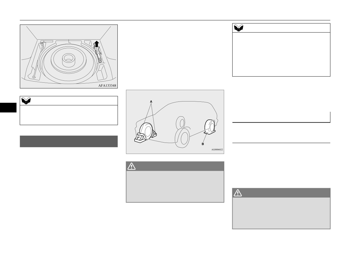
NOTE
set up a warning sign, such as a warning
z The chocks shown in the illustration do not
triangle or flashing signal lights, at an
come with your vehicle. It is recommended
adequate distance from the vehicle, and
that you purchase chocks or blocks and keep
have all your passengers leave the vehicle.
them in the vehicle for use if needed.
5. To prevent the vehicle from rolling when
z If chocks or blocks are not available, use
it is raised on the jack, place chocks or
stones or any other objects that are large
blocks (A) at the tire that is diagonally
enough to hold the wheel in position.
opposite from the tire (B) you are chang-
ing.
6. Get the jack, bar and wheel nut wrench
ready.
NOTE
(Refer to “Jack and tools” on page 8-5.)
8
z
When returning the jack to its original posi-
tion, retract the jack completely. The jack
Spare tire information
may interfere with the luggage floor board.
N00849601341
Compact spare tire
How to change a tire
N00836901904
The compact spare tire is stored under the
Before changing a tire, first stop your vehicle
luggage floor board of the luggage compart-
in a safe, flat location.
ment. It is designed to save space in the lug-
WARNING
gage compartment. Its lighter weight makes it
1. Park the vehicle on level and stable
z Be sure to apply chocks or blocks to the
easier to use if a flat tire occurs.
ground.
correct tire when jacking up the vehicle. If
the vehicle moves while jacked up, the
2. Set the parking brake firmly.
jack could slip out of position, leading to
3. Move the selector lever to the
“P”
WARNING
an accident.
(PARK) position and turn the ignition
z Tires, including the spare tire, degrade
switch (the engine switch) to the “OFF”
over time with age even when they are not
being used. It is recommended that tires
position.
over
6 years old generally be replaced
even if damage is not obvious.
8-6
For emergencies

How to change a tire
CAUTION
CAUTION
To change a tire
z
While the compact spare tire is stowed, the
z
Because the compact spare tire is designed
N00849801604
inflation pressure should be checked at least
only for your vehicle, do not use it on any
1. Loosen the wheel nuts with the wheel nut
once a month to assure that it remains at the
other vehicle.
wrench. Do not remove the wheel nuts
recommended inflation pressure. See the tire
z
Do not put the compact spare tire on a differ-
yet.
and loading information placard attached to
ent wheel, and do not put standard tires,
the driver’s door sill. Refer to
“Tire and
snow tires, wheel covers or trim rings on the
loading information placard” on page 11-3.
compact spare tire. Otherwise, you could
z
Driving with an improperly inflated tire can
damage these parts or other parts on your
cause an accident. If you have no choice but
vehicle.
to drive with an under-inflated tire, keep
z
Do not use tire chains with your compact
your speed down and avoid sudden steering
spare tire. Using a chain could cause damage
or braking, if possible. Inflate the tire to the
to your vehicle and loss of the chains.
correct pressure as soon as possible. Refer to
8
“Tire inflation pressures” on page 9-16.
To remove the spare tire
z
The compact spare tire should be used only
temporarily. While the compact spare tire is
N00849701414
being used, the tire pressure monitoring sys-
1. Lift up the luggage floor board. Refer to
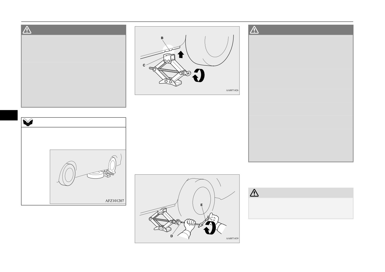
2. Place the jack under one of the jacking
tem will not function properly. Have the tire
“Luggage floor board ” on page 5-230.
points (A) shown in the illustration. Use
replaced or repaired at an authorized
2. To remove the spare tire, remove the
the jacking point closest to the tire you
Mitsubishi Motors dealer or a repair facility
spare tire pad (A), and then remove the
of your choice as soon as possible.
wish to change.
installation clamp (B) by turning it coun-
z
Do not go over 50 mph (80 km/h) when driv-
terclockwise.
ing with the compact spare tire.
z
Avoid sudden starting and braking when
driving with the compact spare tire.
z
Do not drive through automatic car washes
and over obstacles that could possibly dam-
age the underside of your vehicle. Because
the compact spare tire is smaller than the
original tire, there is less clearance between
the ground and your vehicle.
For emergencies
8-7
How to change a tire
WARNING
WARNING
z
Set the jack only at the positions shown
z
Stop jacking up the vehicle as soon as the
here. If the jack is set at a wrong position,
tire is raised off the ground. It is danger-
it could dent your vehicle or the jack
ous to raise the vehicle any higher.
might fall over and cause personal injury.
z
Do not get under your vehicle while using
z
Do not use the jack on a tilted or soft sur-
the jack.
face.
z
Do not bump the raised vehicle or leave it
Otherwise, the jack might slip and cause
sitting on the jack for a long time. Both
personal injury. Always use the jack on a
are very dangerous.
flat, hard surface. Before setting the jack,
z
Do not use a jack except the one that came
make sure there are no sand or pebbles
with your vehicle.
under the jack base.
4. Check that the flange portion at the jack-
z
The jack should not be used for any pur-
pose other than to change a tire.
ing point fits in the groove at the top of
8
z
No one should be in your vehicle when
the jack.
NOTE
using the jack.
Insert the bar
(D) into the wheel nut
z
Put the spare wheel under the vehicle body
z
Do not start or run the engine while your
wrench (E). Then put the end of the bar
near the jack. This makes it safer if the jack
vehicle is on the jack.
into the shaft’s jack end, as shown in the
slips out of position.
z
Do not turn the raised wheel. The tires
illustration.
that are still on the ground could turn and
Slowly rotate the wheel nut wrench until
make your vehicle fall off the jack.
the tire is raised slightly off the ground
surface.
5. Remove the wheel nuts with the wheel nut
wrench, then take the wheel off.
CAUTION
z Handle the wheel carefully when changing
the tire, to avoid scratching the wheel sur-
face.
3. Rotate the jack by hand until the flange
portion (B) fits in the groove (C) at the top
of the jack.
8-8
For emergencies
How to change a tire
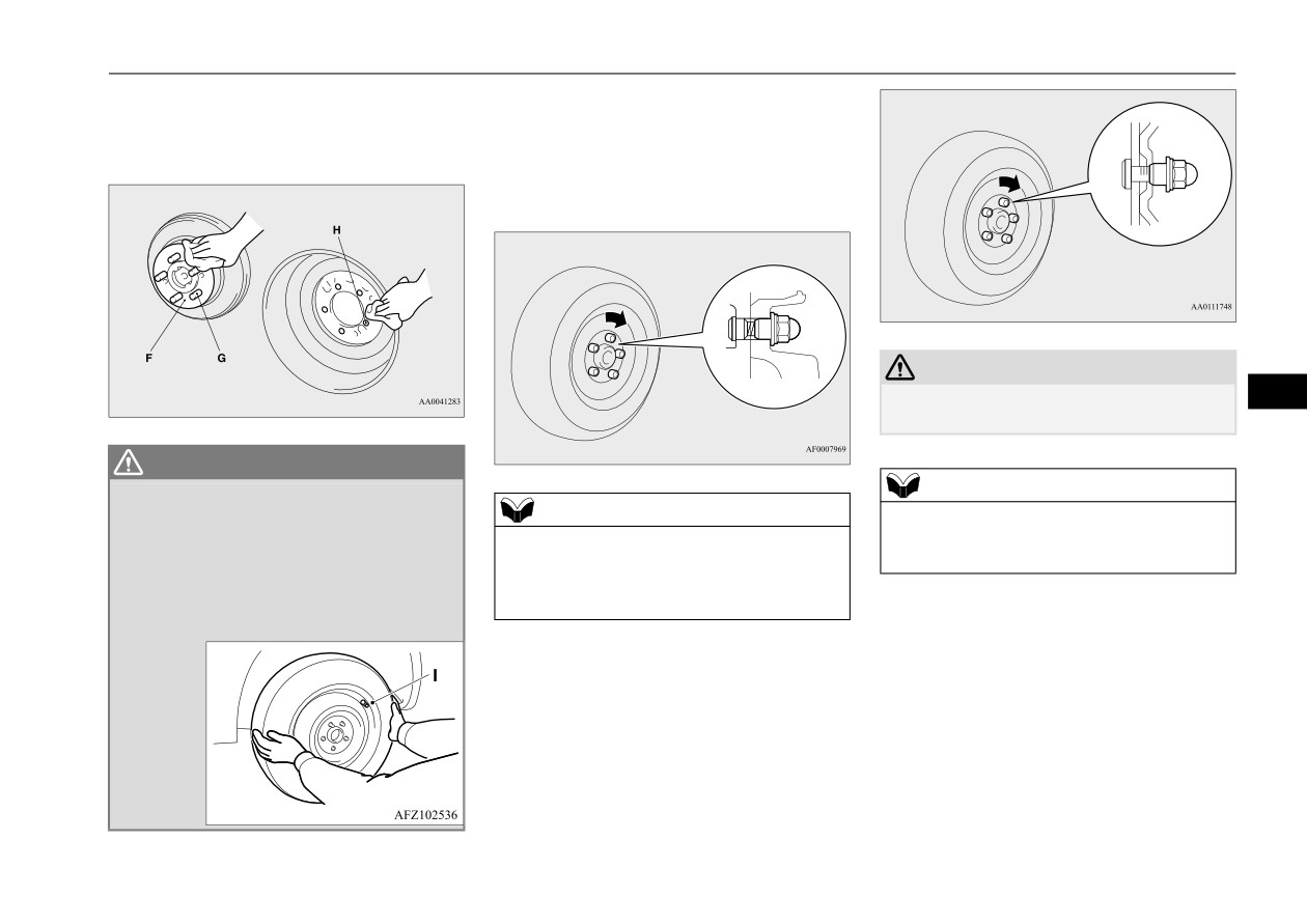
6. Clean out any mud, etc. on the hub sur-
7. Turn the wheel nut clockwise by hand to
face (F), hub bolts (G) or in the installa-
initially tighten them.
tion holes
(H) in the wheel, and then
Temporarily tighten the wheel nuts by
mount the spare tire.
hand until the flange parts of the wheel
nuts make light contact with the wheel
and the wheel is not loose.
CAUTION
z Never apply oil to either the wheel bolts or
8
the nuts or they will tighten too much.
WARNING
z Mount the spare wheel with the valve stem
NOTE
(I) facing outward. If you cannot see the
NOTE
z On vehicles with aluminum wheels, if all 4
valve stem
(I), you have installed the
z Flange nuts can be temporarily used on the
aluminum wheels are changed to steel
wheel backwards.
compact spare tire as shown in the illustra-
wheels, use tapered nuts.
Operating the vehicle with the spare wheel
tion, but return to the original wheel and tire
installed backwards can cause vehicle
as soon as possible.
8. Lower the vehicle slowly until the tire
damage and result in an accident.
touches the ground, by rotating the wheel
nut wrench counterclockwise.
For emergencies
8-9

How to change a tire
10. Lower the jack all the way and remove it.
CAUTION
11. Check the tire inflation pressure. The rec-
z If the steering wheel vibrates when driving
ommended tire pressure
for your vehicle
after changing the tire, have the tire checked
is listed on the tire and loading informa-
for balance at an authorized Mitsubishi
tion placard attached to
the driver’s door
Motors dealer or a repair facility of your
sill as shown in the illustration. Refer to
choice.
“Tire inflation pressures”
on page 9-16.
z Do not mix one type of tire with another or
use a different size from the one listed. This
would cause early wear and poor handling.
To store the spare tire
9. Tighten the nuts in the order shown in the
N00832300059
illustration until each nut has been tight-
1. Lift up the luggage floor board. Refer to
8
ened to the torque listed here.
“Luggage floor board ” on page 5-230.
65 to 80 ft-lb (88 to 108 N•m)
2. Store the spare tire under the luggage
floor board. To store the spare tire, fit the
installation clamp (A) by turning it clock-
wise, and then install the spare tire pad
(B).
CAUTION
z
Driving with an improperly inflated tire can
cause an accident. If you have no choice but
to drive with an under-inflated tire, keep
your speed down and avoid sudden steering
or braking, if possible. Inflate the tire to the
correct pressure as soon as possible. Refer to
“Tire inflation pressures” on page 9-16.
z
After changing the tire and driving the vehi-
CAUTION
cle approximately
620 miles
(1,000 km),
z
Never use your foot or a pipe extension to
retighten the wheel nuts to make sure that
apply added force to the wheel nut wrench
they have not come loose.
when tightening the wheel nuts. If you do so,
you can over-tighten the wheel nuts and
damage the wheel, wheel nuts and hub bolts.
8-10
For emergencies