Mitsubishi Outlander (2022 year). Manual in english - page 10

liftgate is locked. The liftgate can be un-
. pushing the liftgate opener switch
NOTE:
locked and opened independently of the
. pushing the power liftgate close switch
If the pinch sensor is damaged or removed,
other doors, even when they are locked.
on the lower part of the liftgate
the power close function will not operate.
Power close
. pushing the power liftgate button on the
key
WARNING
When the liftgate is fully opened, the liftgate
. the kick motion sensor detects a kicking
will fully close automatically by:
motion (if so equipped) (See “Operating the
There is a small distance immediately before
. pushing the power liftgate switch on the
the closed position that cannot be detected.
power liftgate using the hands-free access”
instrument panel
Make sure that all passengers keep their
(P.3-25).)
. pushing the power liftgate button on the
hands, etc., clear from the liftgate opening
And then the power liftgate will move in the
before closing the liftgate.
key for more than 1 second
reverse direction if one of the above actions is
. pushing the power liftgate close switch
performed again.
on the lower part of the liftgate
The outside chime sounds when the liftgate
The outside chime sounds 3 times when the
CAUTION
starts to reverse.
liftgate starts closing.
Auto reverse function
The safety mechanism will sometimes not
Power close and lock
operate depending on the condition of the
The auto-reverse function enables the liftgate to
When the liftgate is opened, the liftgate will
trapped object or how it is trapped.
automatically reverse when something is caught
fully close and lock automatically by pushing
Therefore, be especially careful not to trap
in the liftgate as it is opening or closing. When
the power liftgate close and lock switch
on
a hand, part of your body or an object at
the control unit detects an obstacle, the liftgate
this time.
the lower part of the liftgate.
will reverse and return to the full open or full
If the safety mechanism is repeatedly
The hazard flashes
2 times and the outside
close position.
activated, the liftgate could be switched
chime sounds when the liftgate starts closing.
If a second obstacle is detected, the liftgate
to manual operation. Once the power
motion will stop. The liftgate will enter the
liftgate is fully opened or closed, normal
Stop and reverse function
automatic operation is possible again.
manual mode.
The power liftgate will stop immediately if one
A pinch sensor is mounted on each side of the
of the following actions is performed during
liftgate. If an obstacle is detected by the pinch
power open or close.
sensor during power close, the liftgate will
. pushing the power liftgate switch
reverse and return to the full open position
immediately.
3-24
Pre-driving checks and adjustments

Manual mode
OPERATING THE POWER
If power operation is not available, the liftgate
LIFTGATE USING THE
can be operated manually. Power operation may
HANDS-FREE ACCESS (if so
not be available if multiple obstacles have been
detected in a single power cycle or if the battery
equipped)
voltage is low. When the power liftgate is
The kick motion sensor
, located on the back
turned off, the liftgate can be opened manually
of the rear bumper, enables you to open or close
by pushing the liftgate opener switch. If the
the liftgate in hands-free.
power liftgate opener switch is pushed during
When you move your foot under and away from
power open or close, the power operation will
the operating range similarly to a kicking
be canceled
and
the
liftgate
can
be
operated
motion, the liftgate will open or close auto-
manually.
matically.
WAD0170X
NOTE:
The kick motion sensor may not function
under the following conditions:
— When operating near a location
where strong radio waves are trans-
mitted, such as a TV tower, power
station, electric vehicle charging sta-
tion or broadcasting station.
— When the vehicle is parked near a
parking meter.
— When wearing a material that hardly
conduct electricity, such as rubber
boots.
— When water adheres to the rear
bumper by washing, rain, etc.
WAD0171X
The power liftgate may not operate when
your foot remains in the operating range.
Pre-driving checks and adjustments
3-25
The kick motion sensor function may not
sensor may be damaged.
LIFTGATE CLOSE AND LOCK
detect a kicking motion underneath a
. Do not perform a kick motion near the
FUNCTION
tow-bar (if so equipped), however the
exhaust system components while they are
normal functionality is retained either
If the liftgate is pulled down to a partly open
hot. You may severely burn yourself.
side of the tow-bar (if so equipped).
position, the liftgate will pull itself to the closed
. Do not perform a kick motion on an
When washing, waxing or maintaining
position.
unstable place (for example, on a slope or
your vehicle, placing or replacing the
a muddy ground, etc.).
Do not apply excessive force when the auto
body cover, or splashing water to the area
closure is operating. Excessive force applied
around the kick motion sensor, turn off
may cause the mechanism to malfunction.
Power open or close function
the power liftgate.
When lots of water splashes the rear
The liftgate will fully open automatically using
the kick motion sensor.
WARNING
bumper by such as heavy rain, etc. Or do
not carry the F.A.S.T. -key within the
1. Carry the F.A.S.T.-key.
Be careful not to trap your hands or fingers
operating range during this time.
2. Move your foot under and away from the
during operation of the liftgate close and lock
rear bumper similarly to a kicking motion
function. If you think this could occur, push a
within the operation range of the kick
power liftgate operation switch or use the
CAUTION
motion sensor.
hands-free access. The power liftgate will
return to the door ajar position.
If the hands-free access remains on, you
3. The liftgate will automatically open or
may be injured due to a sudden operating
close.
of the power liftgate resulting from a
possible reaction of the kick motion sensor.
Stop and reverse function
CAUTION
Refer to “How to turn on/off the power
The power liftgate will stop immediately if a
liftgate” (P.3-22).
kick motion is performed during power open or
. The liftgate will automatically close from a
When the F.A.S.T.-key is carried with you
close.
partly open position. To avoid pinching,
near the liftgate, even someone, who does
keep hands and fingers away from liftgate
And then the power liftgate will move in the
not carry the F.A.S.T.-key, may be able to
opening.
reverse direction if a kick motion is performed
open or close the liftgate with a kick
motion.
again. The power liftgate can be reversed when
. Do not let children operate the liftgate.
you carry the F.A.S.T.-key.
Prevent your foot from touching the rear
bumper during a kicking motion. Other-
wise, the rear bumper and the kick motion
3-26
Pre-driving checks and adjustments

2. Using a suitable tool to open the lid, then
insert the tool in the access opening. Move
the release lever to the left. The liftgate will
be unlatched.
3. Push the liftgate up to open.
Contact an authorized Mitsubishi Motors dealer
as soon as possible for repair.
HEIGHT MEMORY FUNC-
TION
The liftgate can be set to open to a specific
height by performing the following:
1. Open the liftgate.
WAD0279X
WAD0172X
2. Pull the liftgate down to the desired position
LIFTGATE RELEASE LEVER
and hold the liftgate (the liftgate will have
CAUTION
some resistance when being manually
adjusted).
WARNING
Do not touch the latch on the inside of
3. While holding the liftgate in position, press
the power liftgate. Otherwise, your fingers
and hold the power liftgate close switch
Always keep the release lever lid on the liftgate
could trapped in the latch when the liftgate
closed when driving so that your luggage
located on the liftgate for approximately 3
close and lock function operates.
cannot accidentally bump the lever and open
seconds or until 2 beeps are heard.
The liftgate close and lock function oper-
the liftgate.
The liftgate will open to the selected position
ates even when the automatic operation of
setting. To change the position of the liftgate,
the power liftgate is set to OFF. Therefore,
If the liftgate cannot be opened with
,
or
repeat steps 1-3 for setting the position of the
be especially careful not to trap a hand or
finger at this time.
switch (see “Power open (using switches)” (P.3-
liftgate.
23)), due to a discharged battery, follow these
steps.
1. Fold the third row seats down. See “Third
row seats” (P.1-9).
Pre-driving checks and adjustments
3-27
FUEL FILLER DOOR
CAUTION
WARNING
Do not set the height of the liftgate below
. Fuel is extremely flammable and highly
approximately 55 in (1,400 mm) to the floor
explosive under certain conditions. You
using garage mode. Even if you set the height
could be burned or seriously injured if it is
below approximately 55 in (1,400 mm) to the
misused or mishandled. Always stop the
floor, the height will automatically be set to
engine and do not smoke or allow open
approximately 55 in (1,400 mm) to the floor.
flames or sparks near the vehicle when
refueling.
WAD0176X
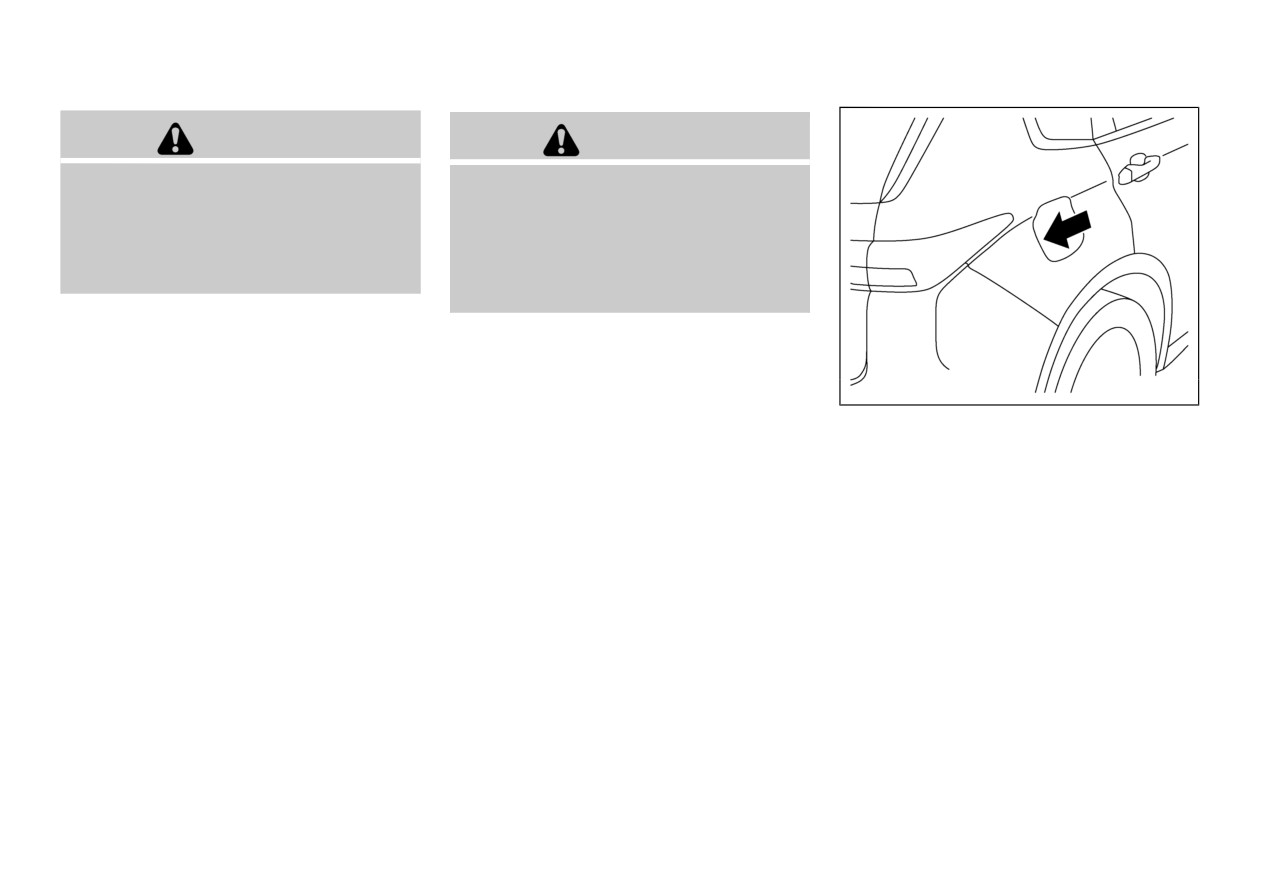
OPENING THE FUEL FILLER
DOOR
The fuel filler door is linked to the vehicle’s
electric door locking mechanism. To open the
fuel filler door, push the rear end of the fuel
filler door when the door lock is released.
NOTE:
If you open the fuel filler door, refuel as soon
as possible.
3-28
Pre-driving checks and adjustments

WAD0177X
JVP0524X
WAD0264X
Instructional label
Instructional label
Emergency opening of the fuel filler
When the fuel tank is filled, the refueling is
HOW TO REFUEL
door
stopped automatically. Pull off the nozzle
This vehicle has the capless fuel filler that does
If you have to open the fuel filler door when the
approximately 5 seconds after the refueling is
not have a fuel filler cap.
automatically stopped.
vehicle battery is discharged, perform the
As illustrated, be sure to insert the fueling
following procedure:
Close the fuel filler door after refueling.
nozzle slowly, in a straight way into the fuel
1. Remove the cover on the right wall of the
filler opening as far as it will go before fueling.
cargo area.
Never move the nozzle during refueling.
CAUTION
2. Operate the rod in the arrow direction by a
suitable tool to unlock the fuel filler door.
. Do not attempt to open the flaps on the fuel
The rod is located behind the seat belt.
filler opening using any tool other than the
fueling nozzle.
Slide the seat belt backwards to approach
the rod.
. Be sure to close the fuel filler door before
using an automatic car wash or a high
Use a flashlight if necessary.
pressure car wash.
Pre-driving checks and adjustments
3-29
If fuel is spilled on the vehicle body, flush it
Be careful not to inhale fuel vapor. Fuel
away with water to avoid paint damage.
contains toxic substances.
Keep the doors and windows closed while
refueling the vehicle. If they were open,
fuel vapor could get into the cabin.
WARNING
Do not attempt to top off/overfill the fuel
tank after the fuel pump nozzle shuts off
Gasoline is extremely flammable and
automatically. Continued refueling may
highly explosive under certain conditions.
cause fuel overflow, resulting in fuel spray
You could be burned or seriously injured if
and possibly a fire.
it is misused or mishandled. Always stop
engine and do not smoke or allow open
Never pour fuel into the throttle body to
flames or sparks near the vehicle when
attempt to start your vehicle.
refueling.
Do not fill a portable fuel container in the
Before opening the fuel filler door, be sure
vehicle or trailer. Static electricity can
WAD0255X
to get rid of your body’s static electricity
cause an explosion of flammable liquid,
by touching a metal part of the vehicle or
vapor or gas in any vehicle or trailer. To
fuel pump. Any static electricity on your
reduce the risk of serious injury or death
CAUTION
body could create a spark that ignites fuel
when filling portable fuel containers:
vapor.
— Always place the container on the
If fuel is spilled on the vehicle body, flush it
Perform the whole refueling process (open-
ground when filling.
away with water to avoid paint damage.
ing the fuel tank filler door, removing the
fuel cap, etc.) by yourself; do not let any
— Do not use electronic devices
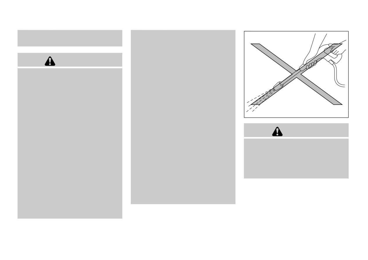
Do not apply direct water pressure, such as
other person near the fuel tank filler. If
when filling.
high-pressure sprayer, on the capless fuel
you allowed a person to help you and that
filler opening when the fuel filler door is
— Keep the pump nozzle in contact
person was carrying static electricity, fuel
opened.
with the container while you are
vapor could be ignited.
filling it.
Do not move away from the fuel tank filler
until refueling is finished. If you moved
— Use only approved portable fuel
away and did something else (for example,
containers for flammable liquid.
sitting on a seat) part-way through the
refueling process, you could pick up a
fresh charge of static electricity.
3-30
Pre-driving checks and adjustments

TILT/TELESCOPIC STEERING
When refueling from a portable fuel
WARNING
container
When refueling from a portable fuel container,
Do not adjust the steering wheel while driving.
use the fuel filler funnel
. The fuel filler
You could lose control of your vehicle and
funnel is stored under the cargo area floor.
cause an accident.
Take out the fuel filler funnel from the cargo
area floor
, push it in to open the inner fuel
lids and refuel
After refueling, remove the funnel from the fuel
filler opening. Wipe the funnel clean and return
it to the storage.
WAD0204X
WAD0254X
Pre-driving checks and adjustments
3-31

SUNVISORS
1. To block glare from the front, swing down
the sunvisor
2. To block glare from the side, remove the
sunvisor from the center mount and swing it
to the side
3. Slide the sunvisor
in or out as needed.
CAUTION
. Do not store the sunvisor before returning
the extension to its original position.
. Do not pull the extension sunvisor forcedly
WAD0246X
downward.
TILT OR TELESCOPIC OP-
ERATION
Pull the lock lever
down and adjust the
steering wheel up, down, forward or rearward to
the desired position. Push the lock lever up
securely to lock the steering wheel in place.
WAD0247X
3-32
Pre-driving checks and adjustments
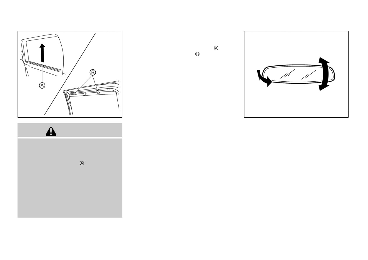
PULL-UP TYPE SUNSHADE
MIRRORS
(rear door) (if so equipped)
The pull-up type sunshades are equipped on the
rear seat windows.
To raise the sunshade, pull the knob up and
push the knob into the hook
To store the sunshade, remove the sunshade
from the hooks and lower it.
WAD0175X
SPA2447
INSIDE MIRROR
CAUTION
Adjust the angle of the inside
mirror
to the
desired position.
Do not pull the sunshade in any direction
other than upward. Doing so may damage
the sunshade.
Do not release the knob when pulling up
or storing the sunshade. If doing so, the
sunshade rolls down rapidly and your
finger may pinched between the sunshade
and the window opening.
Do not drive the vehicle with the windows
open when using the sunshade. Otherwise,
an injury could occur if a gust of wind hits
the shade when it is unhooked, or the
shading parts may get wrinkled.
Pre-driving checks and adjustments
3-33

rearview mirror operate normally. The indicator
light will turn off. Push the
switch again to
turn the system on.
Do not hang any objects on the mirror or
apply glass cleaner. Doing so will reduce the
sensitivity of the sensor
, resulting in
improper operation.
DOOR MIRRORS
WARNING
Objects viewed in the door mirror on the
WAD0248X
WAD0249X
passenger side are closer than they appear. Be
careful when moving to the right. Using only
this mirror could cause an accident. Use the
Manual anti-glare type (if so
Automatic anti-glare type (if so
inside mirror or glance over your shoulder to
equipped)
equipped)
properly judge distances to other objects.
The night position will reduce glare from the
The inside mirror is designed so that it
headlights of vehicles behind you at night.
automatically changes reflection according to
Use the day position when driving in daylight
the intensity of the headlights of the following
vehicle.
hours.
The anti-glare system will be automatically
turned on when the ignition switch is placed in
WARNING
the ON position.
When the anti-glare system is turned on, the
Use the night position only when necessary,
indicator light
will illuminate and excessive
because it reduces rear view clarity.
glare from the headlights of the vehicle behind
you will be reduced.
Push the
switch
to make the inside
3-34
Pre-driving checks and adjustments

Heated door mirrors (if so equipped)
The door mirrors will be heated when the
electric rear window defroster switch is oper-
ated.
(See
“Electric rear window and door
mirror defroster switch” (P.2-52).)
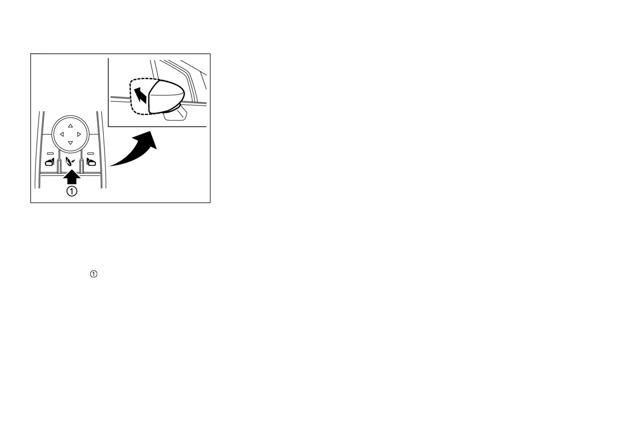
Foldable door mirrors
CAUTION
. Do not drive with the mirrors stored. You
will be unable to see behind the vehicle.
. If the mirrors were folded or unfolded by
WAD0140X
WAD0121X
hand, there is a chance that the mirror will
Example
move forward or backward during driv-
Adjusting door mirrors
ing. If the mirrors were folded or unfolded
Manual type:
The door mirror control switch is located on the
by hand, be sure to adjust them again
Fold the door mirror by pushing it toward the
driver’s armrest.
electrically before driving.
rear of the vehicle.
The door mirror will operate only when the
ignition switch is in the ACC or ON position.
Push the right or left door mirror switch to
select the right or left side mirror
, then adjust
using the control switch.
Pre-driving checks and adjustments
3-35
cycle the mirrors by pushing the door mirror
. The outside mirrors automatically fold
folding switch until the mirrors are in the open
when the ignition switch is placed in the
position.
OFF position, and unfold when the ignition
switch is placed in the ON position.
NOTE:
. Be careful not to get your hands trapped
. The auto fold feature for the outside mirrors
while a mirror is moving.
is disabled.
. If you move a mirror by hand or it moves
Reverse auto tilt function (if so
after hitting a person or object, you may
equipped)
not be able to return it to its original
position using the door mirror folding
When backing up the vehicle, the right or left
switch. If this happens, push the door
door mirrors will turn downward automatically
mirror folding switch to place the mirror
to provide better rear visibility.
in its folded position and then push the
1. Place the ignition switch in the ON position.
WAD0141X
switch again to return the mirror to its
2. Move the shift lever to the R
(Reverse)
original position.
position.
Remote control type:
. When freezing has occurred and mirrors
3. Choose the right or left door mirror by
The door mirror remote control operates when
fail to operate as intended, please refrain
operating the door mirror control switch.
the ignition switch is in the
ACC or ON
from repeated pushing of the door mirror
position.
folding switch as this action can result in
4. The door mirror surface moves downward.
To fold the door mirrors, push the door mirror
burn-out of the mirror motor circuits.
The door mirror surface can be adjusted and
folding switch
. To unfold, push the switch
stored when the reverse auto tilt function is
Folding and unfolding the mirrors
again.
activated. (See “Adjusting door mirrors ” (P.3-
without using the door mirror fold-
35).)
The mirrors automatically retract or extend
ing switch (automatic extension
when the doors are locked or unlocked using the
When one of the following conditions has
key buttons or the F.A.S.T.-key operation. This
function)
occurred, the door mirror surfaces will return
function can be deactivated. See an authorized
Functions can be modified as stated below.
to their original positions.
Mitsubishi Motors dealer for details.
Please consult an authorized Mitsubishi Motors
. Push the right or left door mirror control
If mirrors are manually operated or bumped, the
dealer.
switch again.
mirror body can become loose at the pivot
point. To correct electronic mirror operation,
3-36
Pre-driving checks and adjustments

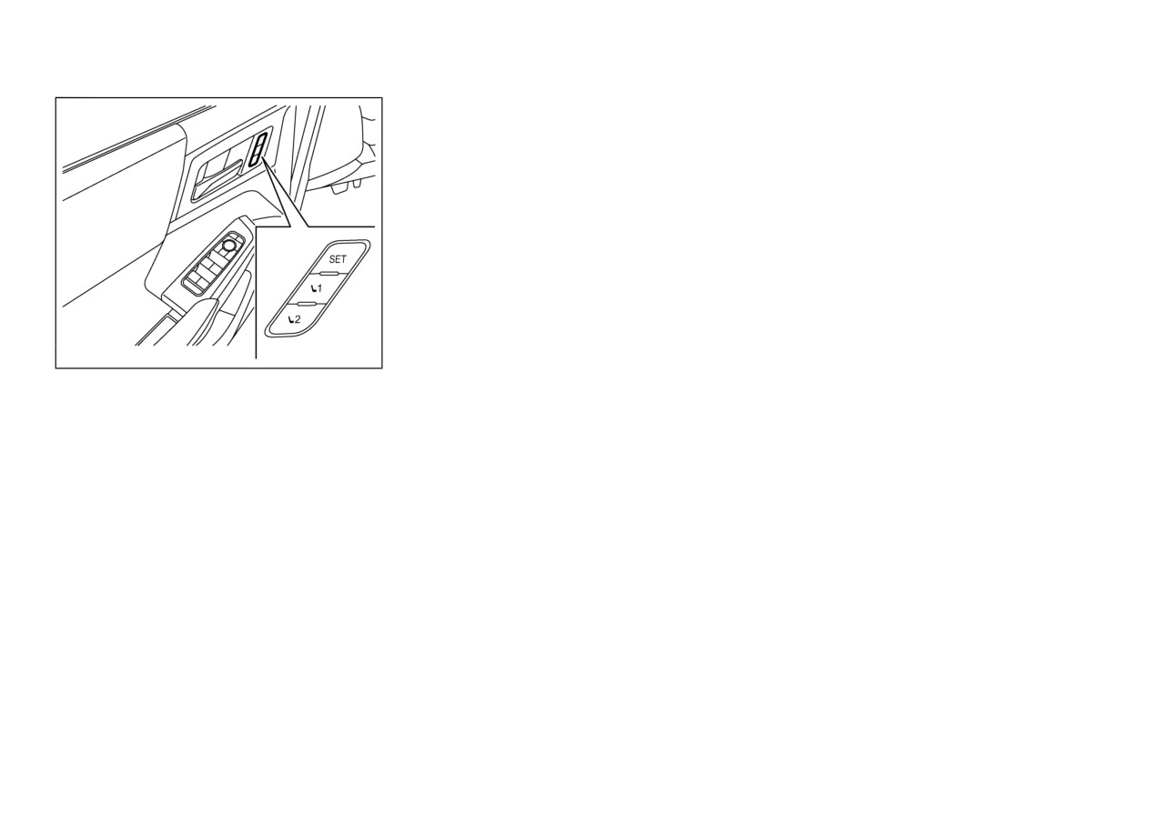
DRIVERMEMORYSETTINGS (if so equipped)
. The shift lever is moved to any position
The driver memory settings has two features:
other than R
(Reverse) and the vehicle
. Memory storage function
speed exceeds 5 MPH (8 km/h).
. Entry/exit function
. After 9 seconds have passed since the shift
lever is moved to any position other than R
(Reverse).
. The ignition switch is placed in the OFF
position.
SIC3869
VANITY MIRROR
To use the front vanity mirror, pull down the
sunvisor and pull up the cover.
Pre-driving checks and adjustments
3-37
3. The indicator light for the pushed memory
Linking log-in function to a stored
switch will come on and stay on for
memory position (models with navi-
approximately 5 seconds.
gation system)
4. The chime will sound if the memory has
The log-in function can be linked to a stored
been stored.
memory position with the following procedure.
NOTE:
1. Place the ignition switch in the ON position
If a new memory position is stored in the
while carrying the F.A.S.T.-key that was
same memory switch, the previous memory
registered to the vehicle with a log-in
position will be overwritten by the new
function.
stored position.
NOTE:
Confirming memory storage
Make sure the F.A.S.T.-key is far apart.
Push the SET switch. If a memory position has
Otherwise, the vehicle may detect the
WAD0142X
not been stored in the switch
(1
or
2) the
wrong F.A.S.T.-key.
indicator light for the respective switch will
2. Adjust the position of the driver’s seat and
MEMORY STORAGE FUNC-
come ON for approximately 0.5 seconds. If a
door mirrors.
(See
“Seats”
(P.1-2) and
TION
memory position has been stored in the switch
“Door mirrors” (P.3-34).)
(1
or
2) then the indicator light for the
Two positions for the driver’s seat and door
3. Place the ignition switch in the OFF
respective switch will stay ON for approxi-
mirrors can be stored in the personal memory.
position.
mately 5 seconds.
Follow these procedures to use the memory
The next time you log in (selecting the user on
system.
Recalling switch memory positions
the display) after placing the ignition switch in
1. Adjust the driver’s seat and door mirrors to
the ON position while carrying the F.A.S.T.-
To recall the manually stored positions, push the
the desired positions by manually operating
key, the system will automatically adjust to the
memory switch (1 or 2). The driver’s seat and
each adjusting switch. For additional in-
memorized driving position. (See the separate
the door mirrors will move to the positions
formation, refer to
“Seats”
(P.1-2) and
Smartphone-link Display Audio (SDA) Own-
stored in the memory switch.
“Door mirrors” (P.3-34).
er’s Manual.)
2. Push the SET switch and, within 5 seconds,
push the memory switch (1 or 2).
3-38
Pre-driving checks and adjustments
Linking an F.A.S.T.-key to a stored
ENTRY/EXIT FUNCTION
SYSTEM OPERATION
memory position (models without
This system is designed so that the driver’s seat
The driver memory settings will not work or
navigation system)
will automatically move when the shift lever is
will stop operating under the following condi-
in the P (Park) position. This allows the driver
tions:
Each F.A.S.T.-key can be linked to a stored
to get into and out of the driver’s seat more
memory position (memory switch 1 or 2) with
When the vehicle is moving. (The driver’s
easily.
the following procedure.
seat returning function can be operated if
The driver’s seat will slide backward:
the vehicle speed is below
2
MPH (3
1. Follow steps 1-3 in the “Memory storage
function” (P.3-38) for storing the memory
. When the driver’s door is opened with the
km/h).)
position.
ignition switch placed in the OFF position.
When any of the memory switches are
pushed while the driver memory settings is
2. The indicator light for the pushed memory
. When the ignition switch is changed from
ON to OFF with the driver’s door open.
operating.
switch will come on. While the indicator
When the switch for the driver’s seat is
light is on for
5 seconds, press the
The driver’s seat will return to the previous
pushed while the driver memory settings is
button and the
button on the F.A.S.T.-
position:
operating.
key in succession. The indicator light of the
. When the ignition switch is placed in the
linked memory switch will blink. After the
When the seat has already been moved to
ON position while the shift position is in the
indicator light goes off, the F.A.S.T.-key is
the memorized position.
P (Park) position.
linked to that memory setting.
When no seat position is stored in the
The entry/exit function can be canceled through
memory switch.
Once it is linked, when ignition switch is placed
“Vehicle Settings” in the multi-information
in the OFF position, pressing the
button on
display by performing the following:
When the shift lever is moved from P (Park)
the F.A.S.T.-key will move the driver’s seat and
to any other position.
. Switch the “Exit Seat Slide” from ON to
door mirrors to the linked memory switch
OFF. For additional information, refer to
position.
“Vehicle Settings” (P.2-26).
NOTE:
If a new memory position is stored in the
linked memory switch, then the F.A.S.T.-key
will link the new position and overwrites the
previous position.
Pre-driving checks and adjustments
3-39
MEMO
3-40
Pre-driving checks and adjustments
4 Monitor, heater, air conditioner, audio and phone systems
Smartphone-link Display Audio (SDA)
How to turn on and off predictive course lines
4-20
4-2
Multi Around Monitor system limitations
4-20
Rearview camera (if so equipped)
4-2
System maintenance
4-22
Rearview camera system operation
4-3
Moving Object Detection (MOD) (if so equipped)
4-23
How to read the displayed lines
4-4
MOD system operation
4-23
Difference between predictive and
Turning MOD on and off
4-25
actual distances
4-4
MOD system limitations
4-25
How to park with predictive course lines
4-6
System maintenance
4-26
Adjusting the screen
4-7
Ventilators
4-26
How to turn ON and OFF predictive course lines
4-8
Center ventilators
4-26
Rearview camera system limitations
4-8
Side ventilators
4-27
System maintenance
4-9
Rear ventilators
4-27
Multi Around Monitor (if so equipped)
4-9
Heater and air conditioner
4-28
Types of views of the Multi Around Monitor
4-11
Dual-zone automatic climate control
4-29
Multi Around Monitor system operation
4-13
3-zone automatic climate control
4-31
Difference between predictive and
Operating tips
4-33
actual distances
4-16
Servicing air conditioner
4-33
How to park with predictive course lines
4-18
Antenna
4-34
How to switch the display
4-19
Shark fin antenna
4-34
Adjusting the screen
4-20
Car phone or CB radio
4-34

SMARTPHONE-LINK DISPLAY
REARVIEW CAMERA (if so equipped)
AUDIO (SDA) OWNER’S MANUAL
Refer to Smartphone-link Display Audio (SDA)
Owner’s Manual that includes the following
information.
Available functions may vary depending on the
models and specifications.
. Audio
. Hands-Free Phone
. Apple CarPlay®
. Android AutoTM
. MITSUBISHI CONNECT powered by
SiriusXM®
. Navigation system
. Voice recognition
. Information and settings viewable on navi-
gation system
WAE0418X
Smartphone-link Display Audio (SDA)
death.
. Rearview camera is a convenience feature
WARNING
and is not a substitute for proper backing.
Always turn and look out the windows,
and check mirrors to be sure that it is safe
. Failure to follow the warnings and instruc-
to move before operating the vehicle.
tions for proper use of the Rearview
Always back up slowly.
camera could result in serious injury or
4-2
Monitor, heater, air conditioner, audio and phone systems

. The system is designed as an aid to the
— Make sure that the liftgate is
driver in showing large stationary objects
securely closed when backing up.
directly behind the vehicle, to help avoid
damaging the vehicle.
The Rearview camera system automatically
. The distance guide line and the vehicle
shows a rear view of the vehicle when the shift
width line should be used as a reference
lever is placed in the R (Reverse) position.
only when the vehicle is on a level paved
surface. The distance viewed on the
The radio can still be heard while the Rearview
monitor is for reference only and may be
camera is active.
different than the actual distance between
the vehicle and displayed objects.
CAUTION
WAE0419X
If the camera lens gets dirty, a clear image
To display the rear view, the Rearview camera
cannot be obtained. As necessary, rinse the
system uses a camera located just above the
lens with clean water and gently wipe with
vehicle’s license plate
a clean, soft cloth.
REARVIEW CAMERA SYS-
To avoid damaging the camera;
TEM OPERATION
— Do not rub the cover excessively
or polish it by using an abrasive
When the ignition switch is placed in the ON
compound.
position, move the shift lever to the R (Reverse)
position to operate the Rearview camera.
— Do not disassemble the camera.
The rearview image will be displayed on the
— Do not splash hot water directly
Smartphone-link Display Audio (SDA) screen.
on the lens.
— Do not spray the camera and its
surroundings with high-pressure
water.
Monitor, heater, air conditioner, audio and phone systems
4-3

Predictive course lines
:
Indicate the predictive course when backing up.
The predictive course lines will be displayed on
the monitor when the shift lever is in the R
(Reverse) position and if the steering wheel is
turned. The predictive course lines will move
depending on how much the steering wheel is
turned and will not be displayed while the
steering wheel is in the straight ahead position.
The vehicle width guide lines and the width of
the predictive course lines are wider than the
actual width and course.
DIFFERENCE BETWEEN
WAE0368X
WAE0559X
PREDICTIVE AND ACTUAL
HOW TO READ THE DIS-
A: Actual objects
DISTANCES
B: Objects shown on the screen
PLAYED LINES
The displayed guidelines and their locations on
Guiding lines which indicate the vehicle width
the ground are for approximate reference only.
Backing up on a steep uphill
and distances to objects with reference to the
Objects on uphill or downhill surfaces or
When there is an upward slope behind the
bumper line are displayed on the monitor.
projecting objects will be actually located at
vehicle, objects shown on the screen will appear
Distance guide lines:
distances different from those displayed in the
to be farther off than they actually are.
monitor relative to the guidelines
(refer to
Indicate distances from the vehicle body.
illustrations). When in doubt, turn around and
. Red line
: approximately 1.5 ft (0.5 m)
view the objects as you are backing up, or park
. Yellow line
: approximately 3 ft (1 m)
and exit the vehicle to view the positioning of
. Green line
: approximately 7 ft (2 m)
objects behind the vehicle.
Vehicle width guide lines
:
Indicate the vehicle width when backing up.
4-4
Monitor, heater, air conditioner, audio and phone systems