Mitsubishi Mirage (2022 year). Manual in english - page 7

Forward Collision Mitigation system (FCM) (if so equipped)
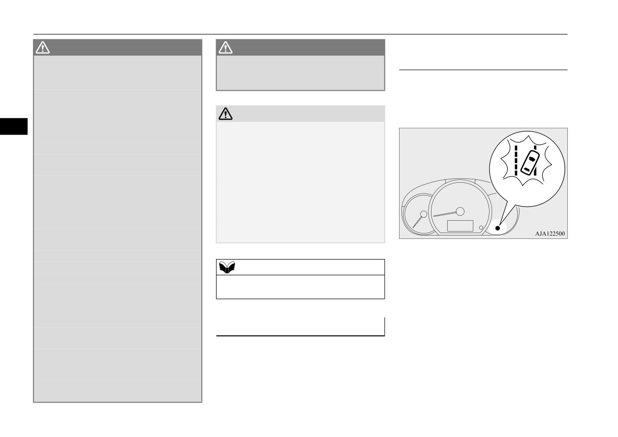
The FCM indicator will blink and the FCM
NOTE
NOTE
OFF indicator will illuminate.
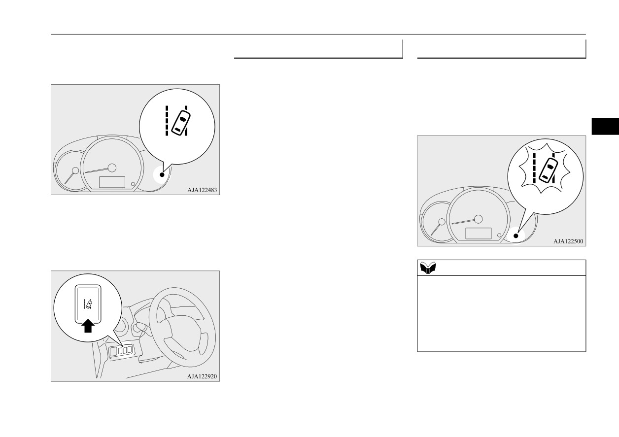
z On vehicles with Lane Departure Warning
z If the sensor or its surrounding area becomes
(LDW), if the LDW is ON, the Lane Depar-
extremely high temperature when parking
ture Warning light (yellow) will blink at the
the vehicle under a blazing sun, the indica-
same time.
tors may illuminate.
If the indicators remain even after the tem-
perature of the sensor or its surrounding area
FCM deactivation due to fault
is within normal range, please contact an
5
N00595300084
authorized Mitsubishi Motors dealer.
If the FCM detects a malfunction in the sys-
tem, the following indicators will illuminate,
and the FCM will automatically be turned off.
When the sensor performance returns, the
FCM functions will resume operation.
If the indicators remain, there is a possibility
that the sensor has a malfunction. Contact an
authorized Mitsubishi Motors dealer for
inspection of the sensor.
NOTE
z The indicators may temporarily blink and
illuminate when the sensor cannot detect a
If the indicators remain even after the ignition
vehicle, a pedestrian or an object within
switch is turned to the “OFF” position and
range. This is not a malfunction. When a
then turned back to the “ON” position or the
vehicle or an object comes within range, the
operation mode is put in OFF and then turned
FCM function will resume and the indicators
back to ON, please contact your authorized
will go off.
Mitsubishi Motors dealer.
z The indicators may blink and illuminate
when driving on a nonbusy road with a few
vehicles and obstacles in front.
5-66
Features and controls

Forward Collision Mitigation system (FCM) (if so equipped)
Handling of the sensor
CAUTION
CAUTION
N00593400140
• Do not apply an impact or load on the sen-
• Do not install an electronic device, such as
The sensor (A) is located inside the wind-
sor or its surrounding area.
antenna, or a device that emits strong elec-
shield as shown in the illustration.
• Do not put anything including a sticker or
tric waves, near the sensor.
The sensor is shared in the following sys-
film to the outer side of the windshield in
• Always use tires of the same size, same
tems:
front of or surrounding area of the sensor.
type and same brand, and which have no
Also, do not put anything including a
significant wear differences.
z
FCM
sticker or film to the inner side of the wind-
• Do not modify the vehicle’s suspensions.
5
z
Lane Departure Warning (LDW) (if
so
shield under the sensor.
z
If the windshield on the sensor or in the sur-
equipped)
rounding area of the sensor is cracked or
scratched, the sensor may not detect an
z
Automatic
High
Beam
(AHB)
(if
so
object properly. This could cause a serious
equipped)
accident. Turn off the FCM and have your
vehicle inspected as soon as possible at an
authorized Mitsubishi Motors dealer.
If you need to replace the windshield, con-
tact an authorized Mitsubishi Motors dealer.
z
The sensor emits infrared rays when the igni-
• Do not attempt to detach or disassemble the
tion switch is turned to the “ON” position or
sensor.
the operation mode is put in ON. Do not look
• If the windshield is misted, remove the mist
into the sensor by using optical goods such
from the windshield by using the defogger
as a magnifying glass. The infrared ray
switch.
might injure your eyes.
• Maintain the wiper blades in good condi-
tion. Refer to “Wiper blades” on page 9-41.
Laser radar specifications
When replacing the wiper blades, use only
Mitsubishi Motors Genuine parts or equiva-
CAUTION
lent.
FDA Assertion number: 1520863-000
z
To maintain proper performance of the FCM,
• Do not dirty or damage the sensor.
LDW and AHB;
Laser classification
• Do not spray glass cleaner on the sensor.
• Always keep clean the windshield.
Also, do not spill liquid, such as a bever-
If the inside of the windshield where the
age, to the sensor.
Max average power
45 mW
sensor is installed becomes dirty or fogged,
contact an authorized Mitsubishi Motors
Pulse duration
33 ns
dealer.
Features and controls
5-67

Lane Departure Warning (LDW) (if so equipped)
Wavelength
905 nm
Lane Departure Warning
Divergent angle
28° x 12°
(LDW) (if so equipped)
(horizon x vertical)
N00577900147
The Lane Departure Warning (LDW) is a
Laser classification label
driving aid system to help prevent uninten-
tional lane departure. The LDW is designed
For vehicles sold in U.S.A.
to read lane markers by using a sensor (A)
5
under certain conditions. The LDW will give
you both visual and audible warnings when
your vehicle is leaving or has left the lane.
WARNING
z
Never rely solely on the LDW. The LDW is
not a collision avoidance system and is not
a substitute for your safe and careful driv-
ing.
For vehicles sold in Canada
z
Before using the LDW, read this entire
section to understand the limitations of
this system. Failure to follow instructions
could result in an accident.
To turn on/off the LDW
Laser explanatory label
NOTE
z The LDW is turned on when the vehicle is
shipped from the factory.
z The currently selected LDW setting (on or
off) is stored even when the ignition switch
is turned to the “OFF” position or the opera-
tion mode is put in OFF.
5-68
Features and controls
Lane Departure Warning (LDW) (if so equipped)
To turn on the LDW, press the LDW switch.
Operation of the LDW
Lane departure warning
The LDW indicator (green) in the meter clus-
N00581100108
N00581200095
ter will illuminate.
While the Lane Departure Warning indicator
The LDW, when turned ON, is capable of
(green) in the meter cluster is lit, if your vehi-
recognizing the lane in which your vehicle is
cle is leaving or has left the lane, a buzzer
travelling and issuing an audible warning
will sound intermittently and the Lane Depar-
when your vehicle begins to leave that travel
ture Warning light (yellow) will blink rapidly.
lane. The LDW will not operate, however, if
any of following conditions have occurred:
5
Green
z
The vehicle speed is less than approxi-
mately 38 mph (60 km/h).
z
The turn signal lever is being operated or
has been operated in the past 7 seconds.
z
The hazard warning light is being oper-
Yellow
To turn off the LDW, press the LDW switch.
ated or has been operated in the past 7
The LDW indicator (green) in the meter clus-
seconds.
ter will then go out.
To return the LDW to “ON”, press the LDW
switch again.
NOTE
z
The warnings will not continue for more than
3 seconds, even if your vehicle continues
leaving the lane.
z
If the lane markers are only on one side of
the road, the LDW will operate only for the
appropriate side where the lane marker is
drawn.
Features and controls
5-69
Lane Departure Warning (LDW) (if so equipped)
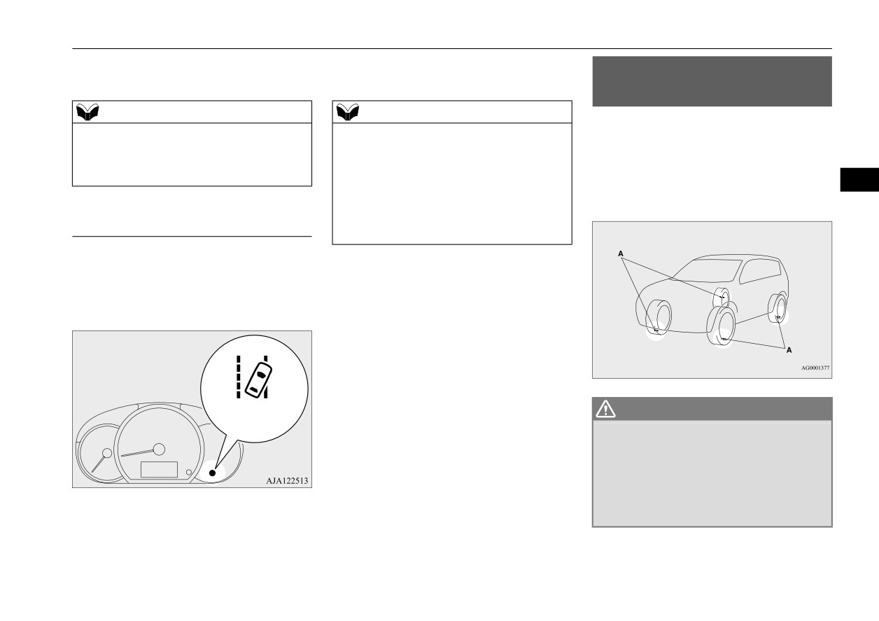
WARNING
WARNING
When the sensor cannot detect
z
The LDW will not function when no lane
• When the front windshield is not clean.
accurately
marker exists, such as at an intersection
• When the front windshield wipers do not
N00598600020
or near a toll booth.
clean the windshield properly.
If the LDW system determines that its perfor-
z
The LDW may not operate correctly in the
mance has been degraded, the Lane Depar-
following situations and the LDW may not
ture Warning light (yellow) will blink slowly.
give warnings or may give false warnings:
CAUTION
• When lane markers are not clearly visi-
5
z
To maintain proper function of the LDW:
ble due to rain, snow, fog, dark area, etc.
• Always keep the windshield and the head-
• When the road surface is shiny.
lights clean.
• When old lane markers remain on the
• Do not put anything, such as a sticker, on
road surface.
the front windshield in front of the sensor.
• When the lane markers are double lines
• Avoid applying a shock or load to the sen-
or the shape of the lane markers are
sor.
Yellow
complicated.
• Do not attempt to detach or disassemble the
• When driving in an extremely narrow
sensor.
lane.
• Use only Mitsubishi Motors Genuine parts
• When the distance between your vehicle
when replacing the windshield wipers.
and a vehicle in front is short.
• When driving into the sun light.
This can occur when
• When driving on curves.
NOTE
• When driving on bumpy roads.
z Foreign objects, such as dirt, snow, ice,
z
When driving conditions are not suitable to
• When driving in construction zones.
mist or dew condensation adhere to the
use the LDW, turn off the LDW.
• When passing through a place where the
windshield of the sensor portion.
brightness suddenly changes, such as at
z In adverse weather conditions, such as
the entrance to or exit of a tunnel.
rain, snow, sand storms, etc.
System problem warning
• When the headlights of an oncoming
z A front vehicle or an oncoming vehicle is
N00578100074
vehicle are very bright.
splashing water, snow or dirt.
• When the rear of your vehicle is weighed
If there is a malfunction in the system, the
down with the weight of passengers and
warning light will illuminate or blink depend-
When the sensor performance returns, the
luggage.
ing on the situation.
LDW functions will resume operation.
• When the headlights of your vehicle are
If the warning light remains, there is a possi-
not clean or are not properly aimed.
bility that the sensor has a malfunction. Con-
5-70
Features and controls
Tire pressure monitoring system (TPMS) (if so equipped)
tact an authorized Mitsubishi Motors dealer
rized Mitsubishi Motors dealer for inspection
Tire pressure monitoring
for inspection of the sensor.
of the system.
system (TPMS) (if so equipped)
NOTE
NOTE
N00530201683
z If the Forward Collision Mitigation system
z If the sensor or its surrounding area becomes
The tire pressure monitoring system (TPMS)
(FCM) is ON, the FCM indicator will blink
extremely high temperature when parking
uses tire inflation pressure sensors (A) on the
and the FCM OFF indicator will illuminate
the vehicle under a blazing sun, the warning
wheels to monitor the tire inflation pressures.
at the same time.
light may illuminate.
The system only indicates when a tire is sig-
5
If the warning light remains even after the
nificantly under-inflated.
temperature of the sensor or its surrounding
area is within normal range, please contact
LDW deactivation due to fault
an authorized Mitsubishi Motors dealer.
N00598700021
If the LDW detects a malfunction in the sys-
tem, the Lane Departure Warning light (yel-
low) will illuminate, and the LDW will
automatically be turned off.
WARNING
Yellow
z The compact spare wheel does not have a
tire inflation pressure sensor.
When the spare tire is used, the TPMS will
not work properly.
See an authorized Mitsubishi Motors
If the warning light remains even after the
dealer as soon as possible to replace or
repair the original tire.
ignition switch is turned to the “OFF” posi-
tion and then turned back to the “ON” posi-
tion or the operation mode is put in OFF and
then turned back to ON, contact your autho-
Features and controls
5-71

Tire pressure monitoring system (TPMS) (if so equipped)
NOTE
Tire pressure monitoring sys-
CAUTION
z
The TPMS is not a substitute for regularly
tem warning light
z
If the tire pressure monitoring system warn-
checking tire inflation pressures.
ing light does not illuminate when the igni-
N00532701435
Be sure to check the tire inflation pressures
tion switch is turned to the “ON” position or
as described in “Tires” on page 9-13.
the operation mode is put in ON, it means
z
The tire inflation pressure sensor
(A) is
that the tire pressure monitoring system is
installed in the illustrated location.
not working properly. Have the system
Replace rubber air valve (B) with a new one
inspected by an authorized Mitsubishi
5
when the tire is replaced.
Motors dealer.
For details, please contact your authorized
In such situations, a malfunctioning of the
Mitsubishi Motors dealer.
system may be preventing the monitoring of
the tire pressure. Avoid sudden braking,
sharp turning and high-speed driving.
z
If a malfunction is detected in the tire pres-
sure monitoring system, the tire pressure
monitoring system warning light will blink
When the ignition switch is turned to the
for approximately 1 minute and then remain
“ON” position or the operation mode is put in
continuously illuminated. The warning light
ON, the tire pressure monitoring system
will issue further warnings each time the
warning light normally illuminates and goes
engine is restarted as long as the malfunction
off a few seconds later.
exists.
Check to see whether the warning light goes
If one or more of the vehicle tires (except for
off after few minutes driving.
the spare tire) is significantly under-inflated,
If it then goes off during driving, there is no
the warning light will remain illuminated
problem.
However, if the warning light does not go
while the ignition switch or the operation
off, or if it blinks again when the engine is
mode is in ON.
restarted, have the vehicle inspected by an
Refer to
“If the warning light illuminates
authorized Mitsubishi Motors dealer.
while driving” on page 5-73 and take the nec-
In such situations, a malfunctioning of the
essary measures.
system may be preventing the monitoring of
the tire pressure. For safety reasons, when
the warning light appears while driving,
avoid sudden braking, sharp turning and
high-speed driving.
5-72
Features and controls
Tire pressure monitoring system (TPMS) (if so equipped)
Each tire, including the spare, should be
the system is not operating properly. The
If the warning light illuminates
checked monthly when cold and inflated to
TPMS malfunction indicator is combined
the inflation pressure recommended by the
with the low tire pressure telltale.
while driving
vehicle manufacturer on the vehicle placard
When the system detects a malfunction, the
N00532801566
or tire inflation pressure label. (If your vehi-
telltale will flash for approximately one min-
1. If the tire pressure monitoring system
cle has tires of a different size than the size
ute and then remain continuously illuminated.
warning light illuminates, avoid hard
indicated on the vehicle placard or tire infla-
This sequence will continue upon subsequent
braking, sharp steering maneuvers and
tion pressure label, you should determine the
vehicle start-ups as long as the malfunction
high speeds. You should stop and adjust
the tires to the proper inflation pressure as
5
proper tire inflation pressure for those tires.)
exists.
As an added safety feature, your vehicle has
When the malfunction indicator is illumi-
soon as possible. Adjust the spare tire at
been equipped with a tire pressure monitoring
nated, the system may not be able to detect or
the same time. Refer to “Tires” on page
system (TPMS) that illuminates a low tire
signal low tire pressure as intended.
9-13.
pressure telltale when one or more of your
TPMS malfunctions may occur for a variety
tires is significantly under-inflated.
of reasons, including the installation of
NOTE
Accordingly, when the low tire pressure tell-
replacement or alternate tires or wheels on the
z
When inspecting or adjusting the tire pres-
tale illuminates, you should stop and check
vehicle that prevent the TPMS from function-
sure, do not apply excessive force to the
valve stem to avoid breakage.
your tires as soon as possible, and inflate
ing properly. Always check the TPMS mal-
z
After inspecting or adjusting the tire pres-
them to the proper pressure. Driving on a sig-
function telltale after replacing one or more
sure, always reinstall the valve cap on the
nificantly under-inflated tire causes the tire to
tires or wheels on your vehicle to ensure that
valve stem.
overheat and can lead to tire failure.
the replacement or alternate tires and wheels
Without the valve cap, dirt or moisture could
Under-inflation also reduces fuel efficiency
allow the TPMS to continue to function prop-
get into the valve, resulting in damage to the
and tire tread life, and may affect the vehi-
erly.
tire inflation pressure sensor.
cle’s handling and stopping ability. Please
z
Do not use metal valve caps, which may
note that the TPMS is not a substitute for
cause a metal reaction, resulting in corrosion
proper tire maintenance, and it is the driver’s
and damage of the tire inflation pressure sen-
responsibility to maintain correct tire pres-
sors.
sure, even if under-inflation has not reached
z
Once adjustments have been made, the warn-
the level to trigger illumination of the TPMS
ing light will go off after a few minutes of
low tire pressure telltale.
driving.
Your vehicle has also been equipped with a
TPMS malfunction indicator to indicate when
Features and controls
5-73

Tire pressure monitoring system (TPMS) (if so equipped)
2. If the tire pressure monitoring system
NOTE
NOTE
warning light remains illuminated after
z Do not use an aerosol puncture-repair spray
z Tire inflation pressures vary with the ambi-
you have been driving for approximately
on any tire.
ent temperature. If the vehicle is subjected to
20 minutes after you adjust the tire infla-
Such a spray could damage the tire inflation
large variations in ambient temperature, the
tion pressure, one or more of the tires may
pressure sensors.
tire inflation pressures may be under-inflated
have a puncture. Inspect the tire and if it
Have any puncture repaired by an authorized
(causing the warning light come on) when
has a puncture, have it repaired by an
Mitsubishi Motors dealer.
the ambient temperature is relatively low. If
authorized Mitsubishi Motors dealer as
the warning light comes on, adjust the tire
5
soon as possible.
The tire pressure monitoring system may not
inflation pressure.
work normally in the following circum-
stances:
WARNING
Whenever the tires and wheels
z
If the warning light illuminates while you
z
A wireless facility or device using the
are driving, avoid hard braking, sharp
are replaced with new ones
same frequency is near the vehicle.
steering maneuvers and high speeds.
N00532900153
z
Snow or ice is stuck inside the fenders
Driving with an under-inflated tire
and/or on the wheels.
If new wheels with new tire inflation pressure
adversely affects vehicle performance and
z
The tire inflation pressure sensor’s battery
sensors are installed, their ID codes must be
can result in an accident.
is dead.
programmed into the tire pressure monitoring
z
Wheels other than Mitsubishi Motors
system. Have tire and wheel replacement per-
Genuine wheels are being used.
formed by an authorized Mitsubishi Motors
CAUTION
z
Wheels that are not fitted with tire infla-
dealer to avoid the risk of damaging the tire
z
The warning light may not illuminate imme-
tion pressure sensors are being used.
inflation pressure sensors. If the wheel
diately in the event of a tire blowout or rapid
z
Wheels whose ID codes are not memo-
replacement is not done by an authorized
leak.
rized by the vehicle are used.
Mitsubishi Motors dealer, it is not covered by
z
Compact spare tire is fitted on a road
your warranty.
wheel.
NOTE
z
A window tint that affects the radio wave
z
To avoid the risk of damage to the tire infla-
CAUTION
tion pressure sensors, have any punctured
signals is installed.
z The use of non-genuine wheels will prevent
tire repaired by an authorized Mitsubishi
the proper fit of the tire inflation pressure
Motors dealer. If the tire repair is not done by
sensors, resulting air leakage or damage of
an authorized Mitsubishi Motors dealer,
the sensors.
damage to the tire inflation pressure sensor is
not covered by your warranty.
5-74
Features and controls

Rear-view camera
image will be displayed on the screen of the
General information
Location of rear-view camera
DISPLAY AUDIO or the Smartphone-link
N00533001288
Display Audio (SDA).
The rear-view camera (A) is in the liftgate, at
Your tire pressure monitoring system oper-
When the gearshift lever or the selector lever
the left side of the liftgate handle.
ates on a radio frequency subject to Federal
is shifted out of the “R” position, the rear-
Communications Commission (FCC) Rules
view image will go off.
(For vehicles sold in U.S.A.) and Industry
Canada Rules (For vehicles sold in Canada).
WARNING
This device complies with part 15 of FCC
5
z
Never rely solely on the rear-view camera
Rules and Industry Canada licence-exempt
to clear the area behind your vehicle.
RSS standard(s).
Always check visually behind and all
Operation is subject to the following two con-
around your vehicle for persons, animals,
ditions.
obstructions or other vehicles. Failure to
do so can result in vehicle damage, serious
z This device may not cause harmful inter-
injury or death.
ference.
z
The rear-view camera is an aid system for
z This device must accept any interference
backing up, but it is not a substitute for
received, including interference that may
your visual confirmation.
CAUTION
cause undesired operation.
z
The view on the screen is limited, and
z
If the camera lens gets dirty, a clear image
objects outside the view, such as under the
cannot be obtained. As necessary, rinse the
bumper or around either corner of the
lens with clean water and gently wipe with a
WARNING
bumper end, cannot be seen on the screen.
clean, soft cloth.
z Changes or modifications not expressly
z
To avoid damaging the camera;
approved by the manufacturer for compli-
• Do not rub the cover excessively or polish
ance could void the user’s authority to
it by using an abrasive compound.
operate the equipment.
• Do not disassemble the camera.
• Do not splash hot water directly on the lens.
• Do not spray the camera and its surround-
Rear-view camera
ings with high-pressure water.
N00546201431
• Make sure that the liftgate is securely
When the gearshift lever or the selector lever
closed when backing up.
is in the “R” position with the ignition switch
or the operation mode is in ON, the rear-view
Features and controls
5-75

Rear-view camera
Reference lines on the screen
CAUTION
Case 2
z
The rear-view camera uses a wide-angle
Reference lines and upper surface of the rear
lens. As a result, images and distances shown
bumper (A) are displayed on the screen.
on the screen are not exact.
z
Actual distance may be different from dis-
z
The red line (B) indicates approximately
tance indicated by the lines on the screen,
20 inches (50 cm) behind the rear bumper.
depending on the loading condition of the
z
The Green lines
(C) indicate approxi-
vehicle and road surface condition.
5
mately 8 inches (20 cm) outside of the
The reference lines for distance and vehicle
A- Actual objects
width are based on a level, flat road surface.
B- Objects shown on the screen
vehicle body.
In the following cases, objects shown on the
z
Short transverse lines (1 to 3) indicate dis-
screen will appear to be farther off than they
tance from the rear bumper.
actually are.
CAUTION
• When the rear of the vehicle is weighed
z
The reference lines for distance and vehicle
down with the weight of passengers and
width are intended to indicate the distance to
luggage in the vehicle. (Case 1)
a flat object such as a level, flat road surface.
• When there is an upward slope at the back.
They may not indicate correct distance
(Case 2)
depending on the shape of an obstacle.
For example, when there is an object behind
the vehicle that has upper sections projecting
Case 1
in the direction of the vehicle, the reference
lines on the screen will indicate that point A
is the farthest point and point B is the closest
point to the vehicle. In reality, point A and B
are actually the same distance from the vehi-
1:
Approximately at the rear edge of the
cle, and point C is farther off than point A
rear bumper
and B.
2:
Approximately 39 inches (100 cm)
3:
Approximately 79 inches (200 cm)
A- Actual objects
B- Objects shown on the screen
5-76
Features and controls
Instrument cluster
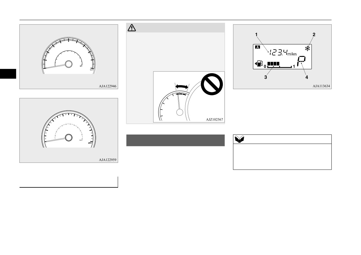
Instrument cluster
Type A
N00519001428
5
NOTE
Type B
z Mirror image is displayed on the screen.
1- Tachometer P.5-78
z Monitor brightness is adjusted automatically
2- Multi-information display P.5-78
by sensors.
3- Speedometer P.5-77
z Under certain circumstances, it may become
4- Multi-information display switch
difficult to see an image on the screen, even
when the system is functioning correctly.
• In a dark area, such as at night.
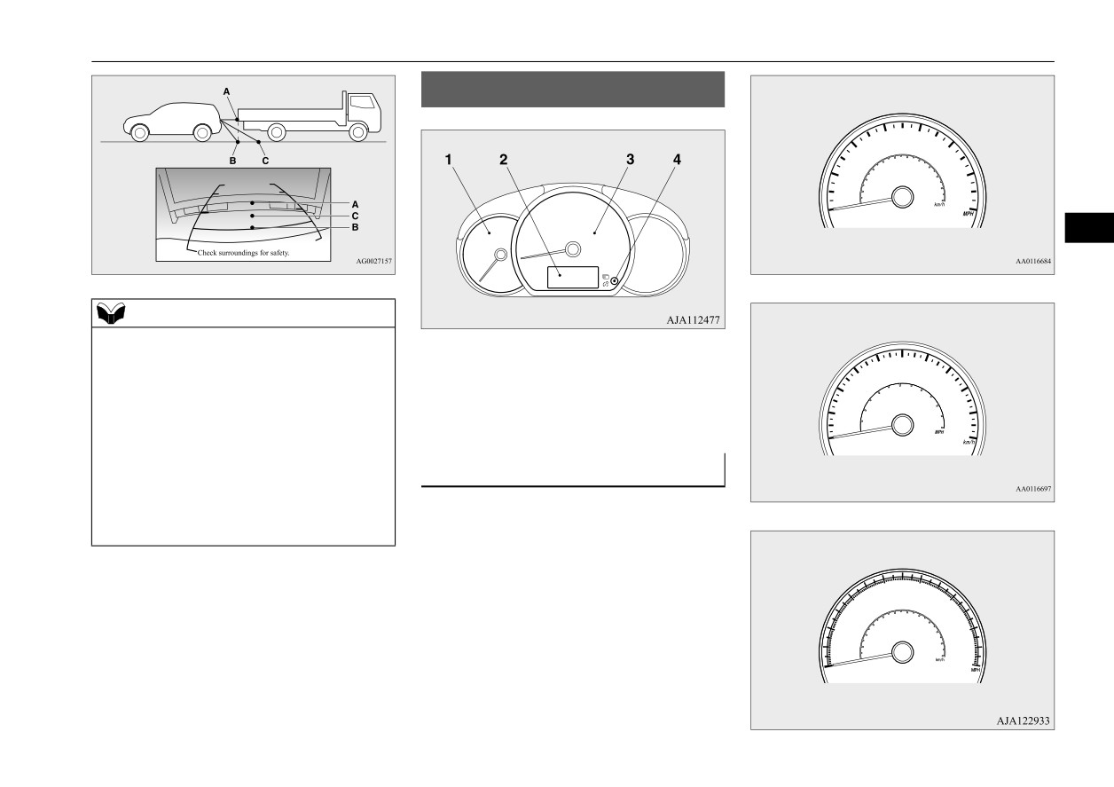
Speedometer
• When water drops or condensation are on
the lens.
N00519101331
• When sun light or headlights shine directly
The speedometer shows the vehicle speed in
into the lens.
miles per hour (mph) or kilometers per hour
Type C
(km/h).
Features and controls
5-77
Multi-information display
Type D
CAUTION
z The red zone indicates an engine speed
beyond the range of safe operation.
Select the correct shift position
(manual
transaxle) or selector position (CVT) to con-
trol the engine speed so that the tachometer
indicator does not enter the red zone.
5
1- Information display P.5-79
2- Frozen road warning P.5-82
Type E
3- Fuel remaining display P.5-82
4- Selector lever position display
(if so
equipped) P.5-45
Multi-information display
NOTE
N00555001536
z
When the ignition switch or the operation
mode is in OFF, the selector lever position
The multi-information display includes the
display, fuel remaining display and frozen
odometer, trip odometer, service reminder,
road warning are not displayed.
fuel remaining, selector lever position, aver-
age fuel consumption, driving range, etc.
Tachometer
N00519201332
The tachometer shows engine revolutions per
minute. This allows the driver to determine
the most efficient selector position and engine
speed combinations.
This gauge also assists in evaluating engine
performance.
5-78
Features and controls
Multi-information display
Information display
N00574801083
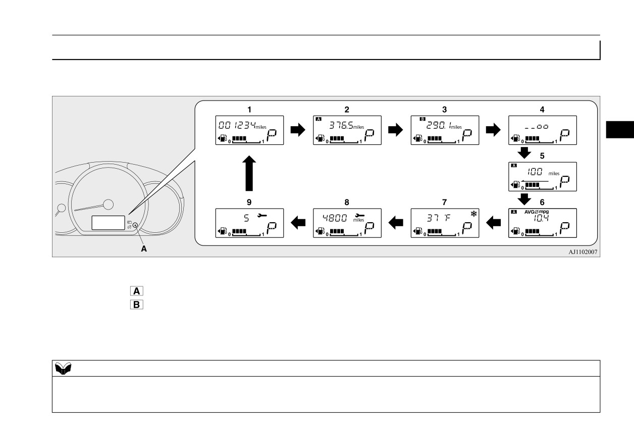
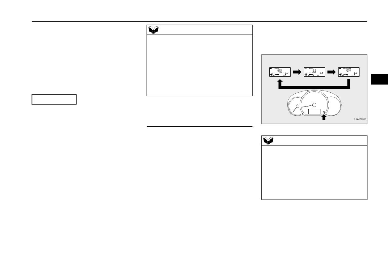
Each time you lightly press the multi-information display switch (A), the display switches in the following order.
5
1- Odometer P.5-80
5- Driving range display P.5-81
6- Average fuel consumption display
2- Trip odometer
P.5-80
P.5-81
3- Trip odometer
P.5-80
7- Outside temperature display P.5-81
4- Instrument panel light dimmer control
8- Service reminder (distance) P.5-83
P.5-80
9- Service reminder (month) P.5-83
NOTE
z When the ignition switch or the operation mode is in OFF, the driving range display, average fuel consumption display and outside temperature display are
not displayed.
z While driving, the service reminder is not displayed even if you operate the multi-information display switch.
Features and controls
5-79

Multi-information display
NOTE
z When the parking lights are not illuminated, the instrument panel light dimmer control is not displayed even if you operate the multi-information display
switch.
If trip odometer
is displayed, only trip
Odometer
Bright
Dim
N00574900016
odometer
will be reset.
The odometer indicates the total distance the
5
vehicle has traveled.
NOTE
z Both trip odometers
and
can count
up to 9999.9 miles/kilometers.
Trip odometer
When a trip odometer goes past
9999.9
N00575000014
miles/kilometers, it returns to 0.0 miles/kilo-
The trip odometer indicates the distance trav-
meters.
eled between two points.
z When disconnecting the battery terminal, the
memories of trip odometer displays
and
1-
Brightness level
Usage examples for trip odometer
, trip
2-
Multi-information display switch
are cleared, and their displays return to
odometer
“0.0 miles/kilometers”.
It is possible to measure two currently trav-
NOTE
eled distances, from home using trip odom-
z
When the parking lights are illuminated, you
eter
and from a particular point on the
Instrument panel light dimmer
can adjust to 8 levels.
way using trip odometer
control
z
Each time you reduce two brightness levels,
N00575101038
the segment display of the brightness level
Turn the parking lights on and press the
decreases by one segment.
z
If you press and hold the switch for longer
multi-information display switch (2), there is
To reset the trip odometer
than about 1 second, the brightness automati-
a sound and the brightness changes.
cally scrolls through its different levels, and
To return the display to 0, hold down the
stops scrolling when you release the switch.
multi-information display switch for about 1
Select your desired level of brightness.
second or more. Only the currently displayed
value will be reset.
Example
5-80
Features and controls

Multi-information display
NOTE
NOTE
NOTE
z The brightness level of the instruments is
z When your vehicle is stopped on an
z
The initial
(default) setting is
“Auto reset
stored when the ignition switch is turned to
extremely steep hill, the driving range value
mode”.
the “OFF” position or the operation mode is
may change. This is due to the movement of
z
Average fuel consumption may vary depend
put in OFF.
fuel in the tank and does not indicate any
on the driving conditions (road conditions,
z On vehicles equipped with the automatic
breakdown.
how you drive, etc.).
light control, the instrument panel light dim-
z The display setting can be changed to the
The actual fuel consumption may differ from
mer control display is not displayed when it
preferred units (miles or km).
the fuel consumption displayed, so treat the
5
is bright outside the vehicle and the ignition
Refer to “Changing the function settings” on
fuel consumption displayed as just a rough
switch or the operation mode is ON.
page 5-84.
guideline.
z
Disconnecting the battery cable will erase
from memory the manual reset mode or auto
Driving range display
Average fuel consumption dis-
reset mode setting for the average fuel con-
N00575201042
play
sumption display.
This displays the approximate driving range
N00575300017
z
The display setting can be changed to the
(how many more miles or kilometers you can
preferred units {mpg, km/L, L/100 km}.
This displays the average fuel consumption
drive). When the driving range falls below
Refer to “Changing the function settings” on
from the last reset to the present.
page 5-84.
approximately 30 miles (50 km), “---” is dis-
The reset mode conditions for the average
played.
fuel consumption display can be switched
between “Auto reset” and “Manual reset”.
Outside temperature display
NOTE
For information on how to change the aver-
N00556501147
z The driving range is determined based on the
age fuel consumption display setting, refer to
Shows the temperature outside the vehicle.
fuel consumption data. This may vary
“Changing the function settings” on page
depending on the driving conditions and hab-
5-84.
NOTE
its. Treat the distance displayed as just a
rough guideline.
z The display setting can be changed to the
NOTE
preferred units (°F or °C).
z When you refuel, the driving range display is
z The average fuel consumption display can be
Refer to “Changing the function settings” on
updated.
reset separately in both auto reset mode and
page 5-84.
However, if you only add a small amount of
manual reset mode.
z Depending on factors such as the driving
fuel, the correct value will not be displayed.
Fill to a full tank whenever possible.
z “---” is displayed when the average fuel con-
conditions, the displayed temperature may
sumption cannot be measured.
vary from the actual outside temperature.
Features and controls
5-81
Multi-information display
turned to the “ON” position or the operation
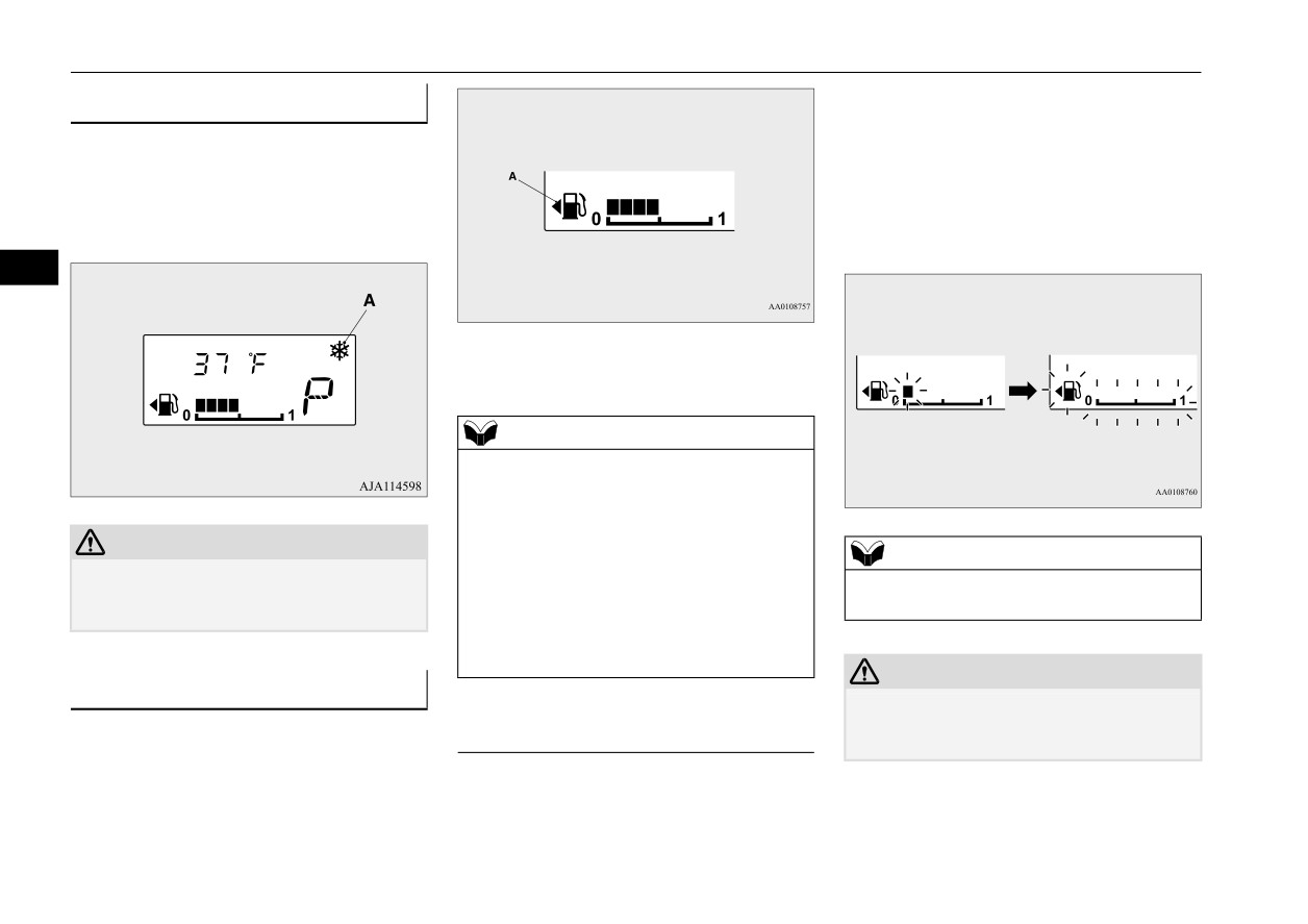
Frozen road warning
mode is changed to ON.
N00579000070
When the remaining fuel level runs very low
If the outside air temperature drops below
(no segments displayed), the bar graph
approx. 37 °F (3 °C), the alarm sounds and
flashes.
the outside air temperature warning symbol
If the warning display appears, refuel imme-
(A) flashes for about 10 seconds.
diately.
5
1- Full
0- Empty
NOTE
z It may take several seconds to stabilize the
display after refilling the tank.
z If fuel is added with the ignition switch or
the operation mode in ON, the remaining
CAUTION
fuel display may incorrectly indicate the fuel
NOTE
z There is a danger the road might be icy, even
level.
z
On hills or curves, the display may be incor-
when this symbol is not flashing, so please
z The fuel lid mark (A) indicates that the fuel
rect due to the movement of fuel in the tank.
take care when driving.
tank filler door is located on the left side of
the vehicle. (Refer to “Filling the fuel tank”
on page 3-3.)
CAUTION
Fuel remaining display
z
Running out of gas could damage the cata-
N00575401044
lytic converter. If the warning display
Fuel remaining warning display
The fuel remaining display indicates the fuel
appears, refuel immediately.
level in the fuel tank when the ignition switch
or the operation mode in ON.
When the remaining fuel level runs low (one
segment is displayed), the last segment of the
fuel gauge flashes when the ignition switch is
5-82
Features and controls

Multi-information display
Service reminder
NOTE
To reset
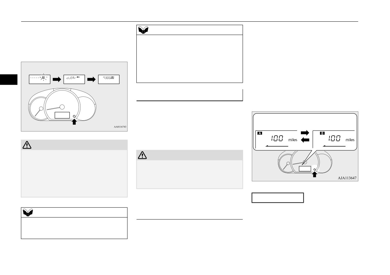
N00556701309
z Shows the distance in units of 100 miles (100
Displays the approximate time until the next
km) and the time in units of 1 month.
The “---” display can be reset while the igni-
recommended periodic inspection.
“---” is
tion switch or the operation mode is in OFF.
displayed when the inspection time has
2. This informs you that a periodic inspec-
1. When you lightly press the multi-informa-
arrived.
tion is due. Contact an authorized
tion display switch a few times, the infor-
Mitsubishi Motors dealer or a repair facil-
mation display switches to the service
5
ity of your choice to have the system
NOTE
reminder display.
checked.
z The service reminder time can be modified
3. After your vehicle is inspected at an
by an authorized Mitsubishi Motors dealer,
authorized Mitsubishi Motors dealer, it
to adjust for severe usage, etc. Refer to
“Severe maintenance schedule” in your vehi-
displays the time until the next periodic
cle’s Warranty and Maintenance Manual. For
inspection.
further information, please contact your
authorized Mitsubishi Motors dealer.
NOTE
z
When the next periodic inspection is
approaching, the wrench symbol will be dis-
Distance
played whenever the ignition switch is
turned from the “OFF” position to the “ON”
position or when the operation mode is
changed from OFF to ON.
The wrench symbol will continuously be dis-
2. Press and hold the multi-information dis-
Month
played, even on non-service reminder dis-
play switch for about 1 second or more to
plays (odometer, trip meter, etc.), until the
make the wrench symbol start flashing. (If
service reminder is reset.
there is no operation for about 10 seconds
When the service reminder resets, the
with flashing, the display will revert to its
wrench symbol will not be displayed until
original indication.)
the next periodic inspection.
1. Shows the time
until the
next
periodic
inspection.
Features and controls
5-83
Multi-information display
3. With this indicator flashing, if you lightly
1. When you lightly press the multi-informa-
NOTE
press the multi-information meter switch,
tion display switch a few times, the infor-
z When “---” is displayed, after a certain dis-
the display switches from
“---”
to
mation display switches to the driving
tance and a certain period of time, the dis-
“cLEAr”. After that, the time until
the
range display.
play is reset and the time until the next
next periodic inspection is shown.
Refer to “Information display” on page
periodic inspection is displayed.
5-79.
z If you accidentally reset the display, consult
2. Each time you press the multi-information
an authorized Mitsubishi Motors dealer for
assistance.
display switch for 1 second or more on
5
driving range display, you can switch
reset mode for average fuel consumption.
Changing the function settings
(A: Auto reset mode, B: Manual reset
N00556801267
mode)
The “Average fuel consumption reset mode”,
“Fuel consumption unit” and “Temperature
unit” setting can be modified as desired,
Auto reset mode
Manual reset mode
when the ignition switch or the operation
mode is ON.
CAUTION
z
The customer is responsible for making sure
CAUTION
that regular inspections and maintenance and
z The driver should not operate the display
periodic inspections and maintenance are
while the vehicle is in motion.
performed.
z When operating the system, stop the vehicle
Inspections and maintenance must be per-
in a safe area.
formed to prevent accidents and malfunc-
tions.
Manual reset mode
Changing the reset mode for aver-
z When the average
fuel consumption is
NOTE
age fuel consumption
being displayed, if you hold down the
z
The “---” display cannot be reset while the
N00575501032
multi-information display switch, these
ignition switch or the operation mode is in
You can change the mode condition for the
calculations will be reset to zero.
ON.
average fuel consumption display to “Auto
z When the following operation is per-
reset” or “Manual reset”.
formed, the mode setting changes auto-
matically from manual to auto.
5-84
Features and controls
Multi-information display
[Except for vehicles equipped with the
3. Press and hold the multi-information dis-
NOTE
F.A.S.T.-key]
play switch to switch in sequence from
z The average fuel consumption display can be
Turn the ignition switch to the “ON” posi-
“km/L”
“L/100
km”
“mpg”
reset separately for the auto reset mode and
tion from the “ACC” or “OFF” position.
“km/L”.
for the manual reset mode.
z Disconnecting the battery cable will erase
[For vehicles equipped with the F.A.S.T.-
from memory the manual reset mode or auto
key]
reset mode setting for the average fuel con-
Change the operation mode to ON from
sumption display.
ACC or OFF.
5
z The initial
(default) setting is
“Auto reset
mode”.
Auto reset mode
z
When the average fuel consumption is
Changing the fuel consumption
being displayed, if you hold down the
display unit
multi-information display switch, these
N00557100156
calculations will be reset to zero.
The fuel consumption display unit can be
z
When the engine switch or the operation
NOTE
changed. The distance and amount units are
mode is in the following conditions, the
also switched to match the selected fuel con-
z
The display units for the driving range, the
average fuel consumption display will
average fuel consumption are changed, but
sumption unit.
automatically reset.
the units for the indicating needle (speedom-
eter), the odometer, the trip odometer and the
1. When you lightly press the multi-informa-
[Except for vehicles equipped with the
service reminder will remain unchanged.
tion display switch a few times, the infor-
F.A.S.T.-key]
z
If the battery is disconnected, the memory of
mation display switches to the average
The ignition switch has been set to the
the unit setting is erased and it returns auto-
fuel consumption display.
“ACC” or “OFF” position for about 4
matically to factory setting.
Refer to “Information display” on page
hours or more.
5-79.
[For vehicles equipped with the F.A.S.T.-
2. Press and hold the multi-information dis-
The distance units is also changed in the fol-
key]
play switch for about 5 seconds or more
lowing combinations to match the selected
The operation mode has been set to ACC
until buzzer sound is heard twice.
fuel consumption unit.
or OFF for about 4 hours or more.
Features and controls
5-85

Multi-information display
Distance
Fuel consumption
(driving range)
km/L
km
L/100 km
km
mpg
mile (s)
5
Changing the temperature unit (if
so equipped)
N00557201183
The temperature display unit can be switched.
1. When you lightly press the multi-informa-
tion display switch a few times, the infor-
mation display switches to the outside
temperature display.
Refer to “Information display” on page
5-79.
2. Each time you press the multi-information
display switch for 5 seconds or more on
outside temperature display, you can
switch from °F to °C or from °C to °F unit
of outside temperature display.
NOTE
z The temperature value on air conditioning
panel is switched in conjunction with outside
temperature display unit of the multi-infor-
mation display.
However, “°F” or “°C” are not shown to tem-
perature display of an air conditioning.
5-86
Features and controls