Mitsubishi Mirage (2022 year). Manual in english - page 5
Free-hand Advanced Security Transmitter (F.A.S.T.-key) (if so equipped)
3. To turn off the alarm, press any button on
General information
Procedure for replacing the
the remote control transmitter.
N00562000065
remote control transmitter bat-
Your F.A.S.T.-key operates on a radio fre-
tery
NOTE
quency subject to Federal Communications
N00562101177
z
The indicator light (4) comes on each time a
Commission (FCC) Rules (For vehicles sold
button is pressed.
in U.S.A.) and Industry Canada Rules (For
WARNING
z
The F.A.S.T.-key can be used from about 40
vehicles sold in Canada). This device com-
z
Do not swallow a coin type battery.
feet
(12 m) away. However, this distance
5
plies with Part 15 of FCC Rules and Industry
• This product contains coin type battery.
may change if your vehicle is near a TV
Canada licence-exempt RSS standard(s).
If a coin type battery is swallowed, it can
transmitting tower, a power station, or a
Operation is subject to the following two con-
cause severe internal burns and can lead
radio station.
ditions.
to death.
z
If the following conditions are observed after
There have been cases where a swallowed
pressing the LOCK (1) or UNLOCK (2) but-
z This device may not cause harmful inter-
battery has caused severe internal burns
ton on the remote control transmitter, the
ference.
in just 2 hours.
buttery in the F.A.S.T.-key may need to be
replaced.
z This device must accept any interference
• Keep new and used batteries away from
children.
• The doors and the liftgate cannot be locked
received, including interference that may
• If the remote control transmitter case
or unlocked.
cause undesired operation of this device.
does not close securely, stop using the
• The panic alarm cannot be operated.
product and keep it away from children.
• The indicator light (4) is dim or does not
WARNING
• If you think batteries might have been
come on.
z
Changes or modifications not expressly
swallowed or placed inside any part of a
z
If you lose your F.A.S.T.-key, please contact
approved by the party responsible for
person’s body, seek immediate medical
an authorized Mitsubishi Motors dealer for a
compliance could void the user’s authority
attention.
replacement.
to operate the equipment.
z
To prevent an explosion or leakage of
z
If you wish to obtain an additional F.A.S.T.-
flammable liquid or gas:
key, please contact an authorized Mitsubishi
• Do not replace the battery with an incor-
Motors dealer. A maximum of four F.A.S.T.-
rect type. Replace only with the same or
key can be programmed for your vehicle.
equivalent type.
z
To use the new remote control transmitters, it
• Do not dispose of a battery into a fire or
is necessary to register the key with the elec-
incinerator, or by mechanically crushing
tronic immobilizer and keyless entry system.
or cutting the battery.
Refer to “Electronic immobilizer (Anti-theft
starting system): Customer F.A.S.T.-key pro-
gramming” on page 5-21.
5-24
Features and controls

Free-hand Advanced Security Transmitter (F.A.S.T.-key) (if so equipped)
3. With the Mitsubishi mark facing you,
5. Install a new battery with the + side (A)
WARNING
insert the cloth-covered tip of a flat blade
up.
• Do not use, store, or take a battery any
screwdriver into the notch in the case and
place where it may be exposed to
+ side
use it to open the case.
extremely high temperature or extremely
low air pressure.
- side
CAUTION
5
z
When the remote control transmitter case is
Coin type
opened, be careful to keep water, dust, etc.
battery
out. Also, do not touch the internal compo-
CR2032
nents.
z
Dispose of used battery according to regula-
tions for the disposal of battery.
6. Close the case firmly.
7. Install the emergency key removed in step
2.
1. Before replacing the battery, remove static
NOTE
8. Check the keyless entry system to see that
electricity from your body by touching a
z
Be sure to perform the procedure with the
it works.
metal grounded object.
Mitsubishi mark facing you. If the
2. Remove the emergency key from the
Mitsubishi mark is not facing you when you
F.A.S.T-key.
NOTE
open the case, the transmitter may come out.
Refer to “Emergency key” on page 5-20.
z You may purchase a replacement battery at
an electric appliance store.
4. Remove the used battery.
z An authorized Mitsubishi Motors dealer can
replace the battery for you if you prefer.
Features and controls
5-25

Door locks
Door locks
To lock and unlock with the key
NOTE
N00509201603
(driver’s door)
z
When locking or unlocking with the key,
only the driver’s door will be locked or
WARNING
unlocked.
Turn the key toward the front of the vehicle to
To lock or unlock all doors and the liftgate,
z
Make sure all doors are tightly closed and
lock the door. After checking that the door is
use the power door lock switches, the key-
locked while driving.
locked, turn the key back to the center and
less entry system or the F.A.S.T-key opera-
• Locked doors, in combination with the
remove it.
tion. (if so equipped)
5
use of seat belts, can help reduce the risk
Refer to “Power door locks” on page 5-27,
of ejection in an accident.
“Keyless entry system” on pages 5-6 and
• Locked doors can help keep passengers,
5-22, and “To operate using the F.A.S.T.-
especially small children, from opening
key” on page 5-12.
doors and falling out of moving vehicles.
z
In vehicles equipped with the F.A.S.T.-key,
• Locked doors can help prevent outsiders
the passenger’s door can be locked and
from gaining access to your vehicle when
unlocked using the emergency key.
you slow or come to a stop.
Refer to “Emergency key” on page 5-20.
z
Lock your vehicle whenever you leave it.
Children who get into unlocked vehicles
may not be able to get out. Children
trapped inside vehicles can quickly be
To lock or unlock the door from
overcome by heat and suffer serious
the inside
injury or death due to heat stroke.
1-
Lock
z
Never leave a child alone in the vehicle. In
2-
Unlock
Move the lock knob to the lock position to
addition to the risk of heat stroke, chil-
dren can activate switches and controls,
lock the door.
resulting in an injury or fatal accident.
All doors should be kept locked while driv-
z
When closing a door, make sure that the
ing.
door is fully closed and the door-ajar
warning display goes out on the informa-
tion screen on the multi-information dis-
play. If the door is ajar it could open while
driving and cause an accident.
5-26
Features and controls

Power door locks
Operation mode ON reminder
system (vehicles equipped with
the F.A.S.T.-key)
N00503800150
If the driver’s door is opened while the engine
is stopped and the operation mode is in any
position other than OFF, the operation mode
5
ON buzzer will sound intermittently to
remind you to put the operation mode in OFF.
1- Lock
2- Unlock
Power door locks
Key reminder system (except
N00509300610
The driver’s door can be unlocked without
for vehicles equipped with the
using the lock knob by pulling on the inside
NOTE
F.A.S.T.-key)
door handle.
z
When locking or unlocking with the key on
N00549600253
the driver’s door, only the driver’s door will
If the ignition switch is turned off and the
lock or unlock.
To lock the door without using
driver’s door is opened with the key in the
z
Repeated continuous operation between lock
the key
ignition switch, the key reminder buzzer will
and unlock could activate the power door
sound intermittently to remind you to remove
locking system’s built-in protection circuit,
1. Move the inside lock knob to the locked
the key.
and prevent the system from operating. If
position.
this occurs, wait about 1 minute before oper-
ating the power door lock switch.
2. Be sure the keys are not inside the vehi-
Lock out protection
cle. Close the door.
N00517300042
If the key is in the ignition switch or the oper-
ation mode is in any mode other than OFF
when you push the lock knob forward with
the driver’s door or passenger’s door open,
the lock knob will automatically return to the
unlocked position.
Features and controls
5-27

Power door locks
To lock and unlock the doors
To unlock the doors and liftgate
Using the selector lever position
and liftgate
N00563401193
{continuously variable transmis-
sion (CVT)}
You can select the functions to unlock the
doors and liftgate either using the ignition
All doors and the liftgate will unlock when
Using the power door lock switch
switch or the engine switch, or using the
the selector lever is moved to the “P” (PARK)
(if so equipped)
selector lever position {continuously vari-
position with the ignition switch or the opera-
able transmission (CVT)}.
5
tion mode in ON.
These functions are not activated when the
vehicle is shipped from the factory. To acti-
vate or deactivate these functions, please
contact your authorized Mitsubishi Motors
dealer.
1- Lock
2- Unlock
All of the doors and the liftgate can be locked
or unlocked by pressing the power door lock
switch on the driver’s or the front passenger
door.
5-28
Features and controls

Child safety locks for rear door
door can be opened using the inside door han-
Child safety locks for rear
WARNING
dle.
z
When opening the liftgate, always fully
door
open it. A partially opened liftgate can
N00509400291
WARNING
unexpectedly close due to its own weight.
z Always keep the doors tightly closed and
z
When the vehicle is parked on a slope, the
locked when driving. An unlocked door
effort required to open or close the liftgate
may be accidentally opened by a passen-
may be greater or less than expected. The
ger, especially by a child who could fall
liftgate may also open or close more
5
out. Also, if the doors are not locked, there
quickly.
is a greater risk of someone being thrown
from the vehicle in an accident.
CAUTION
z
Do not stand behind the exhaust pipe when
Liftgate
loading and unloading luggage. Heat from
the exhaust could lead to burns.
N00510101383
1-
To lock
z
To avoid damage to the liftgate, make sure
2-
To release
that area above and behind the liftgate is
WARNING
clear before opening it.
z
It is dangerous to drive with the liftgate
Child safety locks help prevent rear passen-
open since carbon monoxide (CO) gas can
gers, especially children, from opening the
contained in engine exhaust gases can
enter the passenger compartment.
NOTE
rear door using the inside door handle.
CO is an invisible, odorless gas that can
z
Locking and unlocking the doors by using
A lock lever for the child safety lock is pro-
cause unconsciousness and even death.
the power door lock switch, the keyless entry
vided on each rear door.
z
When opening and closing the liftgate,
system or the F.A.S.T.-key operation also
When the lever is in the lock position (1), the
make sure that there are no people nearby
locks and unlocks the liftgate.
(if so
rear door cannot be opened using the inside
and be careful not to hit your head or
equipped)
door handle.
pinch your hands, neck, etc.
To open the rear door when the child safety
z
If snow or ice has accumulated on the lift-
lock lever is in the lock position, pull the out-
gate, remove it before opening the liftgate.
side door handle.
Otherwise the liftgate may abruptly close
When the lever is in the release position (2),
due to the weight of the snow or ice.
the child safety lock is released and the rear
Features and controls
5-29
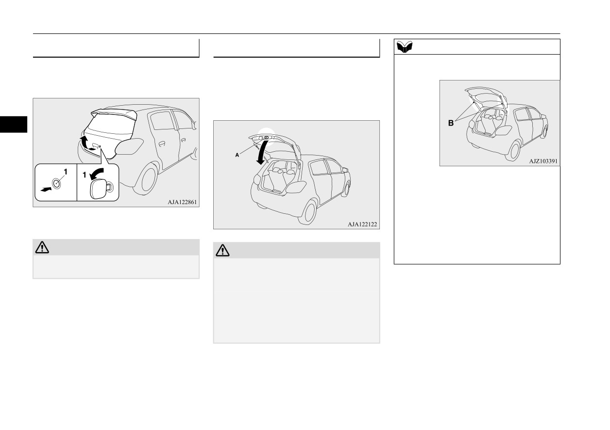
Liftgate
To open
To close
NOTE
z Gas struts (B) are installed in the locations
After unlocking the liftgate, pull the liftgate
Pull the liftgate grip (A) downward as illus-
illustrated in order to support the liftgate.
handle upward to open.
trated and release it before the liftgate closes
completely. Gently slam the liftgate from the
outside so that it is completely closed.
5
Please observe the following in order to pre-
vent damage or faulty operation:
• Do not touch, push or pull the gas struts
when closing the liftgate.
1- Unlock
• Do not attach any plastic material, tape,
etc., to the gas struts.
• Do not tie string, etc., around the gas struts.
CAUTION
CAUTION
• Do not hang objects on the gas struts.
z Make sure there is no one standing nearby
z To avoid injuring your hand or arm, do not
when opening the liftgate.
attempt to close the liftgate without releasing
the liftgate grip (A).
z Before starting the vehicle, be sure to con-
firm that the liftgate is locked. If the liftgate
opens while driving the vehicle, objects
stored in the luggage compartment could fall
out into the road.
5-30
Features and controls

Manual window control (if so equipped)
2-
Close (up)
If the driver’s door window switch is fully
Manual window control (if so
pressed down/pulled up, the driver’s door
equipped)
window automatically opens/closes com-
NOTE
N00510700021
pletely. (Type 1)
z
Never try to operate the main switch and
If the driver’s door window switch is fully
sub-switch in different directions at the same
time. This will freeze the window in posi-
pressed down, the driver’s door window auto-
tion.
matically opens completely. (Type 2)
z
Operating the power windows repeatedly
If you want to stop the window movement,
5
with the engine stopped will run down the
operate the switch lightly in the reverse direc-
battery. Use the window switches only while
tion.
the engine is running.
Type 1
WARNING
z
Before operating the power windows,
1-
To open
make sure that nothing can be trapped
2-
To close
(head, hands, fingers, etc.) in the window.
z
Never leave the vehicle without carrying
the key.
z
Never leave children or unreliable adults
Power window control
unattended inside the vehicle.
N00510800370
Main switch
N00548700130
The main switch located on the driver’s door
can be used to operate all the windows.
A window can be opened or closed by operat-
ing the corresponding switch.
Press the switch down to open the window,
and pull up the switch to close it.
1- Open (down)
Features and controls
5-31

Power window control
stopped. However, once the driver’s door or
Type 2
Sub switch
the front passenger’s door is opened, the
N00548800098
power windows cannot be operated.
Lock switch
N00549000169
When this switch is in the lock mode, the pas-
5
senger door switches cannot be used to open
or close the door windows, and the main
switch will open or close only the driver’s
1-
Driver’s door window switch
door window. To unlock the switch, press it
2-
Front passenger door window switch
again.
3-
Left rear door window switch
1- Close
4-
Right rear door window switch
2- Open
5-
Lock switch
Type 1
Each sub-switch can be used for it’s own pas-
senger door window, unless the driver’s win-
dow lock switch is activated.
Type 2
NOTE
z The rear door windows open only half-way.
1-
Lock
2-
Unlock
Power window timer function
N00548900132
The power windows can be run up or down
when the ignition switch or the operation
mode is in ON.
The door windows can be opened or closed
for a
30-second period after the engine is
5-32
Features and controls

Power window control
WARNING
CAUTION
NOTE
z Before driving with a child in the vehicle,
z
The safety mechanism is deactivated while
z If the battery terminals are disconnected or
be sure to lock the window switch to make
the switch is pulled up. Therefore be espe-
the fuse for electric window is replaced, the
it inoperative. Children tampering with
cially careful that fingers are not trapped in
safety mechanism will be cancelled and the
the switch could easily trap their hands or
the door window opening.
door window will not automatically
heads in the window.
z
Do not deliberately trap your hands or head
open/close completely.
in order to activate the safety mechanism.
If the window is open, repeatedly raise the
Your hand or head could be trapped and per-
driver’s door window switch until the win-
5
sonal injury could result.
dow has been fully closed. Following this,
Safety mechanism (Driver’s
release the switch, raise the switch once
door window of Type 1 only)
again and hold it in this condition for at least
N00528801158
1 second, then release it. You should now be
NOTE
able to operate the driver’s door window in
If a hand or head is trapped, for safety the
z
The safety mechanism can be activated if the
the normal fashion.
door window is automatically lowered a little.
driving conditions or other circumstances
After the door window is lowered, clear the
cause the door window to be subjected to a
obstruction, then pull up the switch again to
physical shock similar to that caused by
What to do if you hear wind
trapped hand or head.
close the door window.
buffeting when driving
z
If the safety mechanism is activated
5 or
N00551400043
more times in a row, the safety mechanism
WARNING
will be cancelled and the door window will
Wind buffeting can be described as the per-
z
If the battery terminals are disconnected
not close correctly. In such a case, the fol-
ception of pressure on the ears or a booming
or the fuse for electric window is replaced,
lowing procedure should be implemented to
or rumbling sound. Your vehicle may exhibit
the safety mechanism will be cancelled.
rectify this situation. If the window is open,
wind buffeting when driving with one or both
If a hand or head got trapped, a serious
repeatedly raise the driver’s door window
rear door windows down or partially opened.
injury could result.
switch until that window has been fully
This is a normal occurrence that can be mini-
closed.
mized. If the buffeting occurs with the rear
Following this, release the switch, raise the
door windows open, open the front door win-
CAUTION
switch once again and hold it in this condi-
tion for at least 1 second, then release it. You
dows as well as the rear door windows to
z
The safety mechanism is deactivated just
should now be able to operate in the normal
minimize the condition.
before the door window closes. This allows
fashion.
the door window to close completely. There-
fore be especially careful that fingers are not
trapped in the door window opening.
Features and controls
5-33
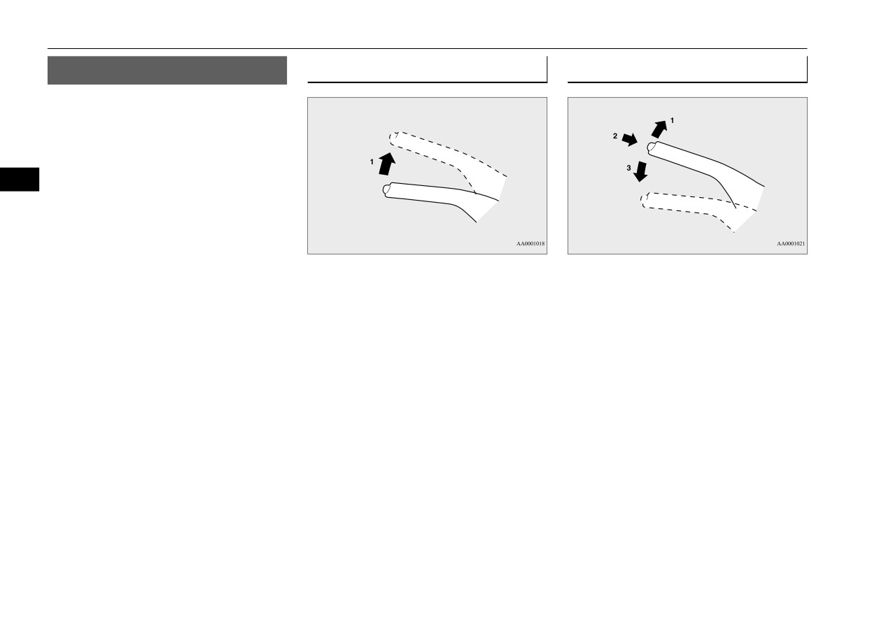
Parking brake
Parking brake
To apply
To deactivate
N00511400399
To park the vehicle, first bring it to a com-
plete stop, fully engage the parking brake,
and then move the gearshift lever to 1st (on a
uphill) or “R” (Reverse) (on a downhill) posi-
tion for vehicles equipped with a manual
5
transaxle, set the selector lever to
“P”
(PARK) position for vehicles equipped with a
continuously variable transmission (CVT).
1- Pull the lever up without pushing the
1- Pull the lever up slightly.
button at the end of hand grip.
2- Press and hold the button at the end of
When the parking brake is set and the
the hand grip.
ignition switch or the operation mode is
3- Push the lever downward.
in the “ON” position, the brake warn-
ing light in the instrument cluster will
When parking on a hill, set the parking brake,
come on.
and turn the front wheels toward the curb on a
downhill, or away from the curb on an uphill.
Before driving, be sure to release the
parking brake.
5-34
Features and controls

Steering wheel height adjustment
CAUTION
Inside rearview mirror
z Before driving, be sure that the parking
N00511601529
brake is fully released and brake warning
Adjust the inside rearview mirror only after
light is off.
making any seat adjustments so as to have a
If you drive without the parking brake fully
clear view to the rear of the vehicle.
released, the warning lamp will illuminate
and a buzzer sounds when the vehicle speed
exceeds 5 mph (8 km/h).
Type 1
5
If a vehicle is driven without releasing the
parking brake, the brakes will be overheated,
resulting in ineffective braking and possible
brake failure.
A- Wheel lock
B- Release
Steering wheel height
Type 2
WARNING
adjustment
z After adjusting, make sure the lever is
N00511500231
secured in the locked (A) position.
To adjust the steering wheel to the desired
z Do not attempt to adjust the steering
position, move the lever upward or down-
wheel while driving. This can be danger-
ous.
ward while moving the steering wheel to the
desired level.
z When releasing the lever (moving it to the
Type 3
position (B)), be sure to hold the steering
wheel firmly. Otherwise, the steering
wheel may slip down too suddenly.
Features and controls
5-35

Inside rearview mirror
WARNING
To adjust the mirror position
To reduce the glare
z Do not attempt to adjust the inside rear-
view mirror while driving. This can be
It is possible to move the mirror up/down and
dangerous.
left/right to adjust its position.
Type 1
Be sure to adjust the mirror before driv-
ing.
The day/night knob (A) at the bottom of the
mirror can be used to adjust the mirror to
Adjust the inside mirror to maximize the
5
reduce the glare from the headlights of vehi-
view through the rear window.
cles behind you during night driving.
To adjust the vertical mirror
position
It is possible to move the mirror up and down
to adjust its position.
1- Daytime position
2- Night position
5-36
Features and controls

Outside rearview mirrors
Type 2
Type 3
NOTE
z
If you want to stop automatic mode, press
When the headlights of the vehicles behind
When the headlights of the vehicles behind
the switch (3) for approximately 2 seconds
you are very bright, the reflection factor of
you are very bright, the reflection factor of
and the indicator (1) will go off.
the rearview mirror is automatically changed
the rearview mirror is automatically changed
To return to automatic mode, press the
to reduce the glare.
to reduce the glare.
switch again or perform the following opera-
tion.
[Except for vehicles equipped with the Free-
5
hand Advanced Security Transmitter
(F.A.S.T.-key)]
Turn the ignition switch to the “ON” position
after turning to “OFF” or “ACC” position.
[For vehicles equipped with the Free-hand
Advanced Security Transmitter
(F.A.S.T.-
key)]
Put the operation mode in ON after putting
the operation mode in OFF.
When the ignition switch is turned to the
Normally, use the automatic mode. When the
Outside rearview mirrors
“ON” position or the operation mode is put in
ignition switch is turned to the “ON” position
N00512200206
ON, the reflection factor of the mirror is auto-
or the operation mode is put in ON, the green
Adjust the outside rearview mirrors only after
matically changed.
indicator
(1) illuminates and the reflection
making any seat adjustments so as to have a
factor of the mirror is automatically changed.
clear view to the rear of the vehicle.
NOTE
z Do not hang items on, or spray glass cleaner
NOTE
WARNING
on the sensor
(1), as reduced sensitivity
z Do not hang items on, or spray glass cleaner
z Do not attempt to adjust the outside rear-
could result.
on the sensor
(2), as reduced sensitivity
view mirrors while driving. This can be
could result.
dangerous.
Be sure to adjust the mirrors before driv-
ing.
Features and controls
5-37
Ignition switch
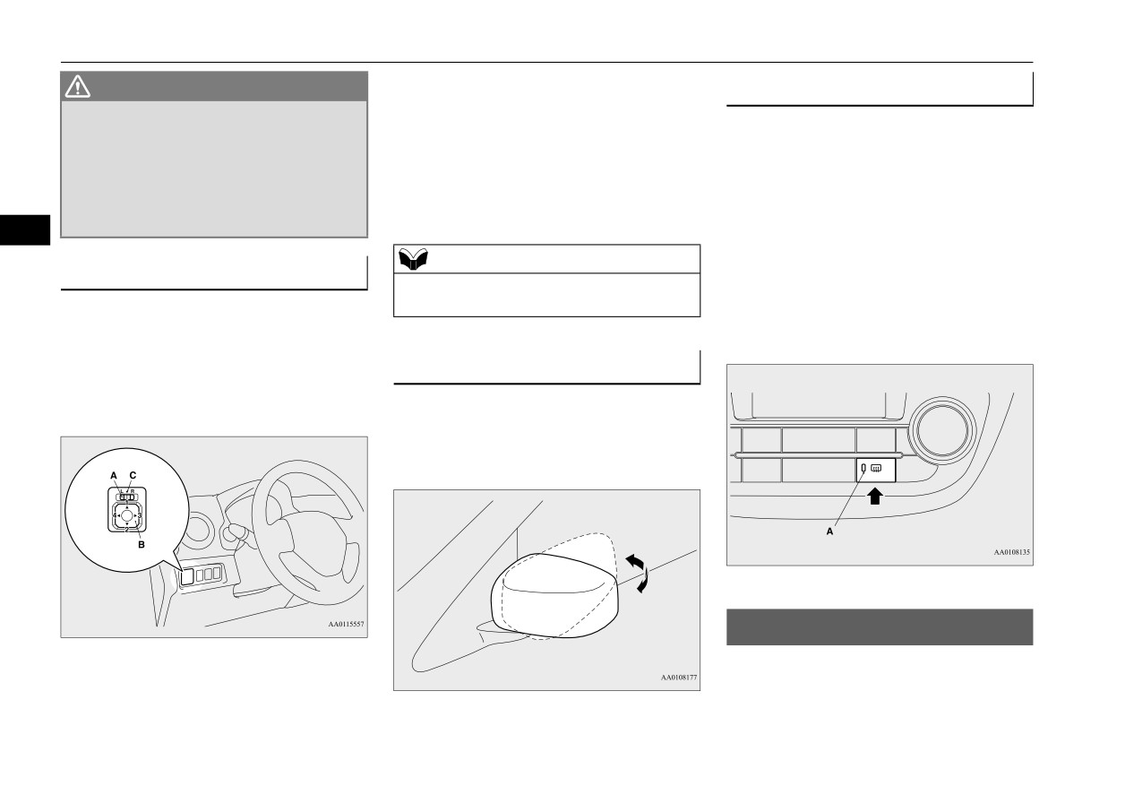
Press the switch (B) to adjust the mirror posi-
WARNING
Door mirror heater (if so equipped)
tion.
z Your passenger’s side mirror is convex.
N00549301286
The objects you see in the mirror will look
1- Up
smaller and farther away than they
When the rear window defogger switch is
2- Down
appear in a regular flat mirror.
pressed with the engine running, the outside
3- Right
Do not use this mirror to estimate the dis-
rearview mirrors are defogged or defrosted.
4- Left
tance of vehicles following you when
Current will flow through the heater element
changing lanes.
inside the mirrors, thus clearing away frost or
5
condensation.
NOTE
The indicator light (A) will illuminate while
To adjust the mirror position
z After adjusting, return the lever to the “•”
the defogger is on.
N00549100144
(OFF) position (C).
The heater will be turned off automatically in
The outside rearview mirrors can be adjusted
about 20 minutes.
when the ignition switch or the operation
mode is in ON or ACC.
To fold the mirror
Move the lever (A) to the same side as the
N00549200099
mirror you wish to adjust.
The outside mirror can be manually folded in
towards the side window to prevent damage
when parking in tight locations.
Ignition switch
N00512401726
L- Left outside mirror adjustment
R- Right outside mirror adjustment
[For vehicles equipped with the Free-hand
Advanced Security Transmitter (F.A.S.T.-
key)]
5-38
Features and controls

Ignition switch
For information on operations for vehicles
2. Turn the key to the “OFF” position and
ACC
equipped with the Free-hand Advanced Secu-
remove it.
rity Transmitter
(F.A.S.T.-key), refer to
“Free-hand Advanced Security Transmitter
Allows operation of some electrical accesso-
(F.A.S.T.-key):
ries with the engine off.
Engine switch” on page 5-14.
ON
[Except for vehicles equipped with the
Free-hand Advanced Security Transmit-
5
The engine runs and all accessories can be
ter (F.A.S.T.-key)]
used.
START
Engages the starter. Release the key when the
CAUTION
engine starts.It will automatically return to
z
If the engine is stopped while driving, the
the “ON” position.
brake servomechanism will cease to function
and braking efficiency will deteriorate. Also,
NOTE
the power steering system will not function
and it will require greater manual effort to
z Your vehicle is equipped with an electronic
operate the steering.
immobilizer. To start the engine, the ID code
which the transponder inside the key sends
z
Do not leave the key in the “ON” position for
must match the one registered to the immobi-
a long time when the engine is not running,
OFF
lizer computer. (Refer to “Electronic immo-
doing so will cause the battery to be dis-
bilizer” on page 5-3.)
charged.
z
Do not turn the key to the “START” position
The engine is off. The key can be inserted and
when the engine is running, doing so could
removed only when the switch is in this posi-
damage the starter motor.
tion.
To remove the key
N00550900201
1. Set the selector lever to the “P” (PARK)
position {continuously variable transmis-
sion (CVT)}.
Features and controls
5-39
Starting the engine
z A longer warm up period will only con-
There is usually no need to depress the accel-
Starting the engine
sume extra fuel. The engine is warmed up
erator pedal when starting the engine.
N00512601861
enough for driving when the low coolant
The starter should not be run for more than 15
[For vehicles equipped with the Free-hand
temperature indicator goes out.
seconds at a time.
Advanced Security Transmitter (F.A.S.T.-
Refer to “Low coolant temperature indi-
To prevent battery drain, wait a few seconds
key)]
cator” on page 5-88.
between attempts to restart the engine.
For information on operation for vehicles
equipped with the Free-hand Advanced Secu-
1. Make sure all occupants are properly
5
WARNING
rity Transmitter
(F.A.S.T.-key), refer to
seated with seat belts fastened.
z
Never run the engine in a closed or poorly
“Free-hand Advanced Security Transmitter
2. Insert the ignition key.
ventilated area any longer than is needed
(F.A.S.T.-key): Starting and stopping the
3. Make sure the parking brake is applied.
to move your vehicle out of the area. Car-
engine” on page 5-17.
4. Press and hold the brake pedal down
bon monoxide gas, which is odorless and
firmly with your right foot.
extremely poisonous, could build up and
[Except for vehicles equipped with the
5. Press and hold the clutch pedal all the way
cause serious injury or death.
Free-hand Advanced Security Transmit-
down (manual transaxle).
ter (F.A.S.T.-key)]
CAUTION
NOTE
z
Do not push-start the vehicle.
z On vehicles equipped with manual transaxle,
Tips for starting
z
Do not run the engine at high rpms or drive
the starter will not operate unless the clutch
z Do not operate the starter motor continu-
at high speeds until the engine has had a
pedal is fully depressed (Clutch interlock).
ously for longer than 15 seconds as this
chance to warm up.
could run the battery down or damage the
z
Release the ignition switch as soon as the
6. On vehicles equipped with manual trans-
starter motor. If the engine does not start,
engine starts. Otherwise, the starter motor
axle, place the gearshift lever in the “N”
will be damaged.
turn the ignition switch back to the “OFF”
(Neutral) position.
position, wait a few seconds, and then try
On vehicles equipped with continuously
again. Trying repeatedly with the engine
variable transmission (CVT), make sure
or starter motor still turning will damage
Starting the engine
the selector lever is in the “P” (PARK)
the starter mechanism.
position.
z If the engine will not start because the bat-
This model is equipped with an electronically
tery is weak or discharged, refer to
controlled fuel injection system. This is a sys-
“Jump-starting the engine” (on page 8-2)
tem that automatically controls fuel injection.
for instructions.
5-40
Features and controls
Manual transaxle (if so equipped)
2. While depressing the brake pedal {contin-
NOTE
Startability of CVT vehicle with
uously variable transmission (CVT)} or
z On vehicles equipped with CVT, the starter
ambient temperature of -4 °F (-20
the clutch pedal (manual transaxle), press
will not operate unless the selector lever is in
the accelerator pedal halfway and hold it
°C) or lower
the “P” (PARK) or “N” (NEUTRAL) posi-
there, then crank the engine. Release the
tion.
accelerator pedal, immediately after the
When the ambient temperature is -4 °F (-20
For safety reasons, start the engine in the “P”
(PARK) position so that the wheels are
engine starts.
°C) or lower, it may not be possible to start
locked.
3. If the engine still will not start, the engine
from a standstill even with the selector lever
5
could be flooded with too much gasoline.
in the
“D” (DRIVE) or “R” (REVERSE)
While depressing the brake pedal (CVT)
position.
7. Turn the ignition switch to the “ON” posi-
or the clutch pedal
(manual transaxle),
This phenomenon occurs because the trans-
tion and make certain that all warning
push the accelerator pedal all the way
axle has not warmed up sufficiently; it does
lights are functioning properly before
down and hold it there, then crank the
not indicate a problem. If this occurs, place
starting the engine.
engine for 5 to 6 seconds. Return the igni-
the selector lever in the “P” (PARK) position
8. Turn the ignition switch to the “START”
tion switch to the
“OFF” position and
and let the engine idle for at least 10 minutes.
position without pressing the accelerator
release the accelerator pedal. Wait a few
The transaxle will warm up, and you will be
pedal. Release the key when the engine
seconds, and then crank the engine again
able to start normally.
starts.
for 5 to 6 seconds while depressing the
Do not leave the vehicle during warm-up
brake pedal (CVT) or the clutch pedal
operation.
NOTE
(manual transaxle), but do not push the
z Minor noises may be heard on engine start-
accelerator pedal. Release the ignition
up. These will disappear as the engine warms
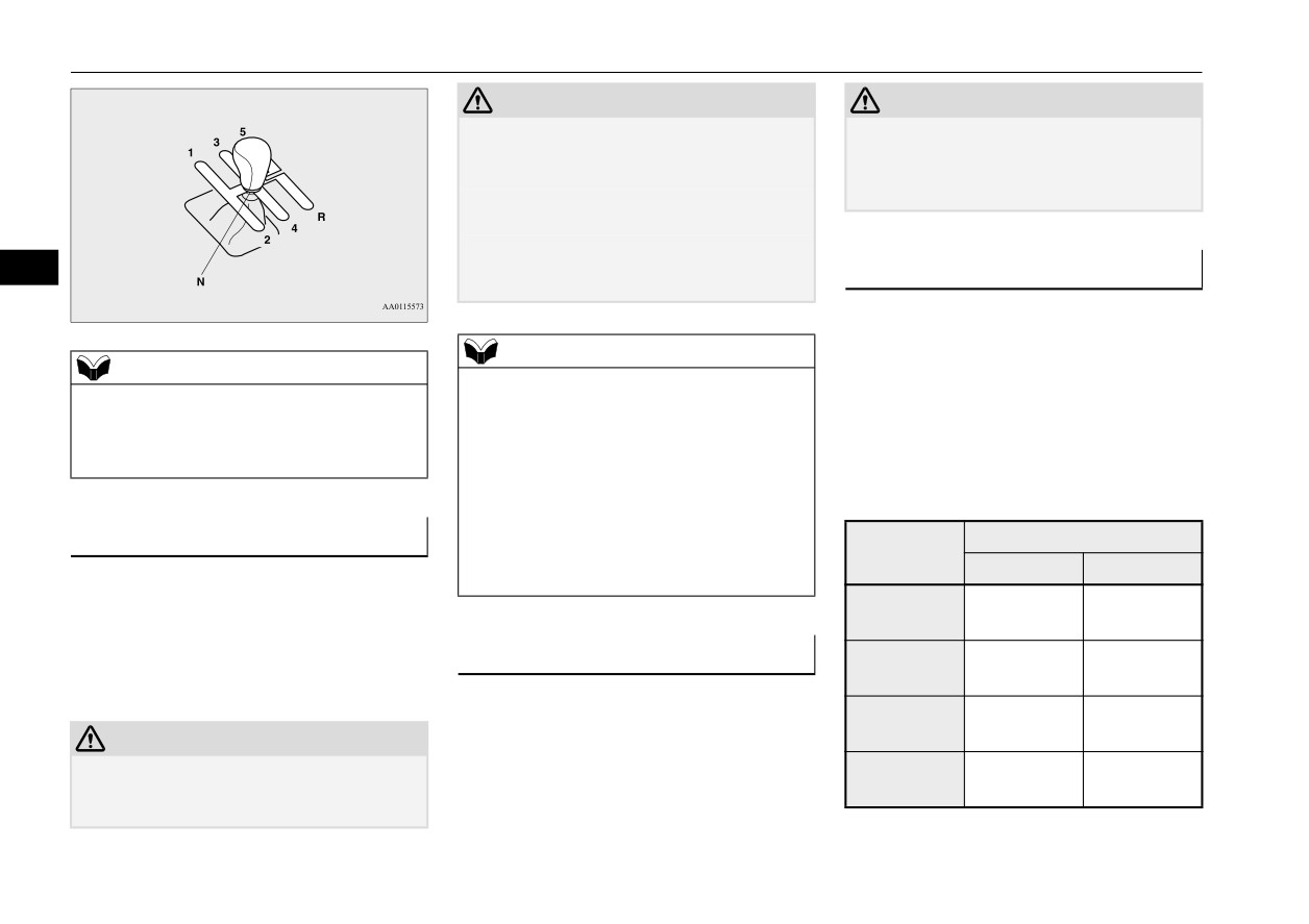
Manual transaxle (if so
switch if the engine starts. If the engine
up.
fails to start, repeat these procedures. If
equipped)
the engine still will not start, contact your
N00512701224
local Mitsubishi Motors dealer or a repair
When the engine is hard to start
The shift pattern below is shown on the gear-
facility of your choice for assistance.
shift lever. Press the clutch pedal all the way
After several attempts, you may experience
down while shifting gears.
that the engine still does not start.
1. Make sure that all electric devices, such
as lights, air conditioning blower and rear
window defogger, are turned off.
Features and controls
5-41
Manual transaxle (if so equipped)
CAUTION
CAUTION
z
Do not rest your foot on the clutch pedal
z Avoid downshifting that may cause the
because this will cause premature clutch
tachometer pointer to enter the red zone.
wear or damage.
This puts the engine at risk of being dam-
z
Do not coast in the “N” (Neutral) position
aged.
(illegal in many states).
z
Do not use the gearshift lever as a handrest,
because this can result in premature wear of
5
Upshifting
the transaxle shift forks.
N00512900131
For the best fuel economy and performance in
using your manual transaxle, upshift as listed
NOTE
NOTE
below.
z
If it is hard to shift into
1st, depress the
z
During cold weather, shifting may be diffi-
clutch pedal a second time; the shift will then
At low altitude locations, shift at the vehicle
cult until the transaxle lubricant has warmed
be easier.
up. This is normal and not harmful to the
speeds listed. Upshifting earlier during cruise
z
To shift into reverse from 5th gear, move the
transaxle.
conditions
(relatively steady speeds) will
gearshift lever to the “N” (Neutral) position,
improve your fuel economy.
and then shift it into reverse.
z
To avoid grinding noises when shifting into
To start
reverse, wait approximately 3 seconds with
Upshift speeds
Shift point
the clutch pedal depressed when the vehicle
Acceleration
Cruise
is stationary.
Press the clutch pedal all the way down and
1st gear to
15 mph
15 mph
shift into 1st or “R” (Reverse) position, oper-
2nd gear
(24 km/h)
(24 km/h)
ating the gearshift lever slowly. Then gradu-
Proper shift points
2nd gear to
28 mph
19 mph
ally release the clutch pedal while depressing
N00537400065
3rd gear
(45 km/h)
(31 km/h)
the accelerator pedal.
Always use care to change the gear with the
3rd gear to
36 mph
33 mph
vehicle speed matched to the engine speed.
4th gear
(58 km/h)
(53 km/h)
CAUTION
Proper shifting will improve fuel economy
z Do not move the gearshift lever into reverse
4th gear to
45 mph
45 mph
and prolong engine life.
while the vehicle is moving forward; doing
5th gear
(72 km/h)
(72 km/h)
so will damage the transaxle.
5-42
Features and controls
Continuously variable transmission (CVT) (if so equipped)
At high altitude locations, upshift as listed
Downshifting speed
Shift point
Continuously variable
below.
20 to 30 mph (32 to
Shift down from cur-
transmission (CVT) (if so
48 km/h)
rent gear to 3rd gear.
Shift point
Upshift speeds
equipped)
1st gear to 2nd gear
15 mph (24 km/h)
N00560200050
Driving precautions
2nd gear to 3rd gear
25 mph (40 km/h)
N00513100244
The CVT will automatically and continuously
3rd gear to 4th gear
40 mph (64 km/h)
z Do not use the gearshift lever as a han-
change its gear ratio depending on road and
5
4th gear to 5th gear
45 mph (72 km/h)
drest. This can result in premature wear of
driving conditions. This helps achieve
the transaxle shift forks.
smooth driving and excellent fuel efficiency.
Downshifting
Maximum possible driving speed
DRIVING UPHILL
N00513000096
It is recommended that you downshift to a
Shift
Maximum possible driving
The transmission prevents unnecessary
lower gear when needed to maintain the
points
speed
upshifts even when the accelerator pedal is
desired speed, according to the table.
released and ensures smooth driving.
Avoid downshifting at too high a speed. The
1st gear
28 mph (45 km/h)
engine may suffer damage.
2nd gear
53 mph (85 km/h)
To maintain a safe speed and prolong brake
DRIVING DOWNHILL
3rd gear
78 mph (125 km/h)
life, shift down to 2nd or 1st when descend-
ing a steep hill.
4th gear
105 mph (170 km/h)
According to the conditions, the transmission
Downshifting is also important to avoid “lug-
will automatically shift to a lower gear ratio
ging” the engine at too low a speed, such as
z The table above shows the maximum rec-
to achieve stronger engine braking. This may
when turning a corner or when driving up a
ommended driving speed for in each gear.
help reduce your need to use the service
steep hill.
Do not drive near or at these speeds for
brake.
prolonged periods of time.
Recommended downshifting speed
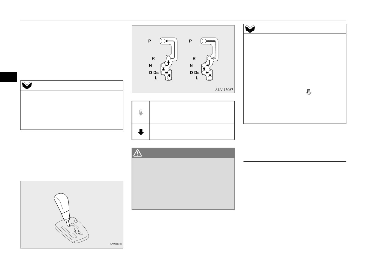
Selector lever operation
N00560301087
Downshifting speed
Shift point
As an additional safety precaution, models
equipped with a continuously variable trans-
Under 20 mph
Shift down from cur-
mission have a shift-lock device that holds
(32 km/h)
rent gear to 2nd gear.
Features and controls
5-43
Continuously variable transmission (CVT) (if so equipped)
the selector lever in the “P” (PARK) position.
NOTE
To move the selector lever from the
“P”
z
To prevent mistakes in operating the lever,
(PARK) position to another position, follow
make sure you stop briefly at each position.
the steps below.
After operating, check the position in the
multi-information display.
1. Press and hold the brake pedal down.
z
If the brake pedal is not depressed and held,
2. Move the selector lever to the desired
the shift-lock device activates to prevent the
position.
selector lever from being moved from the
5
“P” (PARK) position.
NOTE
z For a shift indicated by
in the illustra-
z The selector lever cannot be moved from “P”
(PARK) to another position if the ignition
tion, depress the brake pedal before moving
Set the selector lever in the gate to
switch is set to the “OFF” or “ACC” posi-
the selector lever. If you attempt to move the
tion, or if the key has been removed, or oper-
operate while the brake pedal is
selector lever before depressing the brake
ation mode is in “OFF” or “ACC”, or if the
depressed.
pedal, the selector lever may not move.
brake pedal is not pressed and held down.
Set the selector lever in the gate to
operate.
When the selector lever cannot be
The CVT selects an optimum ratio automati-
cally when the selector lever is in the “D”
shifted from the “P” (PARK) posi-
WARNING
(DRIVE) position, depending on the speed of
tion
z
Always press the brake pedal when shift-
the vehicle and the position of the accelerator
N00563300049
ing the selector lever into a selector posi-
pedal.
When the selector lever cannot be shifted
tion from the “N” (NEUTRAL) position.
from the
“P” (PARK) position to another
When beginning to drive, do not shift the
selector lever from the “N” (NEUTRAL)
position while the brake pedal is pressed and
position while pressing the accelerator
held down with the ignition switch or the
pedal. This will cause the vehicle to
operation mode in ON, the battery may be flat
“jump” forward or backward.
or the shift-lock mechanism may be malfunc-
tioning.
Immediately have your vehicle checked by an
authorized Mitsubishi Motors dealer or a
repair facility of your choice.
5-44
Features and controls