Mitsubishi L200 (2020 year). Manual in english - page 20

Fuses
10 A: Option
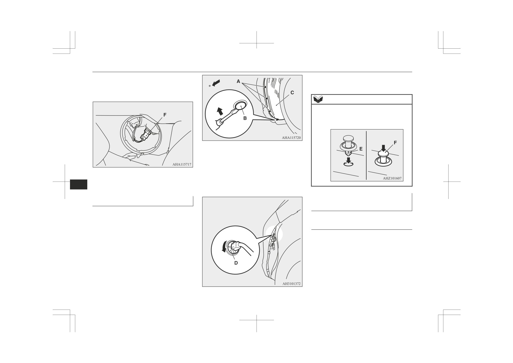
2. Remove the fuse puller (A) from the in-
NOTE
15 A: Cigarette lighter
side of the fuse box in the engine com-
z
If any system does not function but the fuse
When using a substitute fuse, replace with a
partment.
corresponding to that system is normal, there
fuse of the correct capacity as soon as possi-
may be a fault in the system elsewhere. We
ble.
recommend you to have your vehicle
checked.
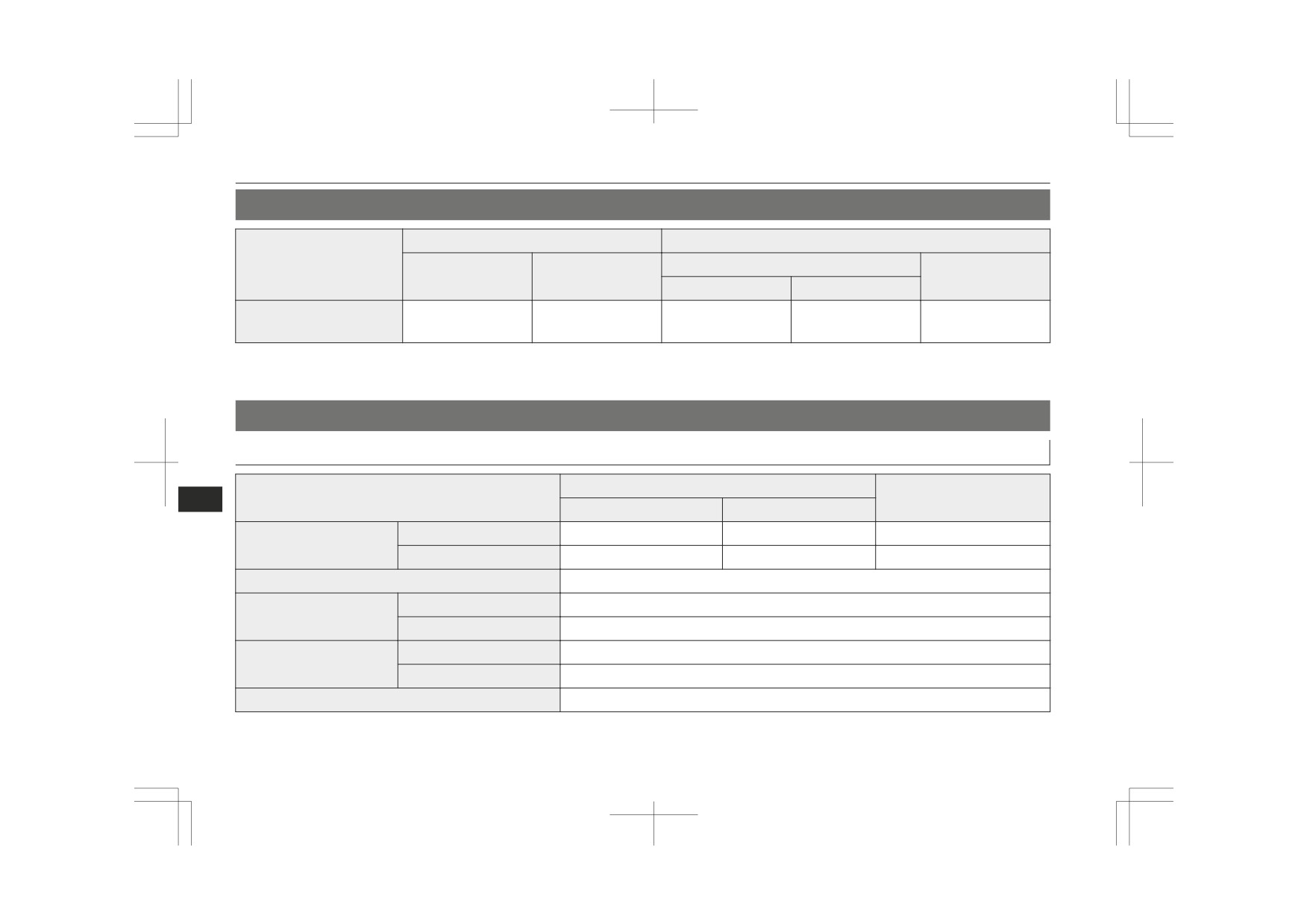
Identification of fuse
Ca-
Colour
4. Insert a new fuse of the same capacity
pacity
by using the fuse puller into the same
place at the fuse block.
7.5 A
Brown
10 A
Red
15 A
Blue
20 A
Yellow
3. Referring to the fuse load capacity table,
Green (fuse type) / Pink (fusible
30 A
check the fuse pertaining to the problem.
10
link type)
40 A
Green (fusible link type)
Fuse replacement
1. Before replacing a fuse, always turn off
CAUTION
the electrical circuit concerned and place
z If the newly inserted fuse blows again after a
the ignition switch in the “LOCK” posi-
short time, we recommend you to have the
tion or put the operation mode in OFF.
electrical system checked to find the cause
and rectify it.
z Never use a fuse with a larger capacity than
specified or a substitute (such as a cable or
B- Fuse is OK
foil). Doing so could cause the circuit wires
C- Blown fuse
to overheat and create a fire.
Maintenance
10-23
Replacement of lamp bulbs
Replacement of lamp bulbs
CAUTION
NOTE
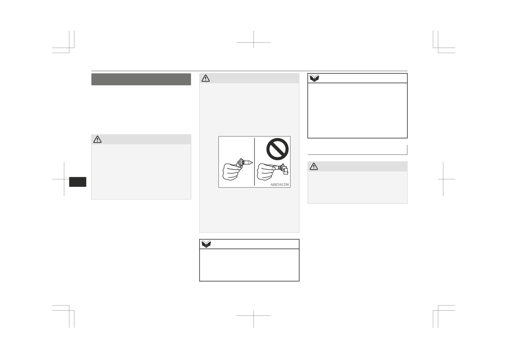
z
Never hold the halogen lamp bulb with a
z When it rains or when the vehicle has been
Before replacing a bulb, ensure the lamp is
bare hand, dirty glove, etc.
washed, the inside of the lens sometimes be-
off. Do not touch the glass part of the new
The oil from your hand could cause the bulb
comes foggy. This is the same phenomenon
bulb with your bare fingers; the skin oil left
to break the next time the headlamps are op-
as when window glass mists up on a humid
on the glass will evaporate when the bulb
erated.
day, and does not indicate a functional prob-
If the glass surface is dirty, it must be
lem. When the lamp is switched on, the heat
gets hot and the vapour will condense on the
cleaned with alcohol, paint thinner, etc., and
will remove the fog. However, if water gath-
reflector and dim the surface.
refit it after drying it thoroughly.
ers inside the lamp, we recommend you to
have the lamp checked.
CAUTION
z
Bulbs are extremely hot immediately after
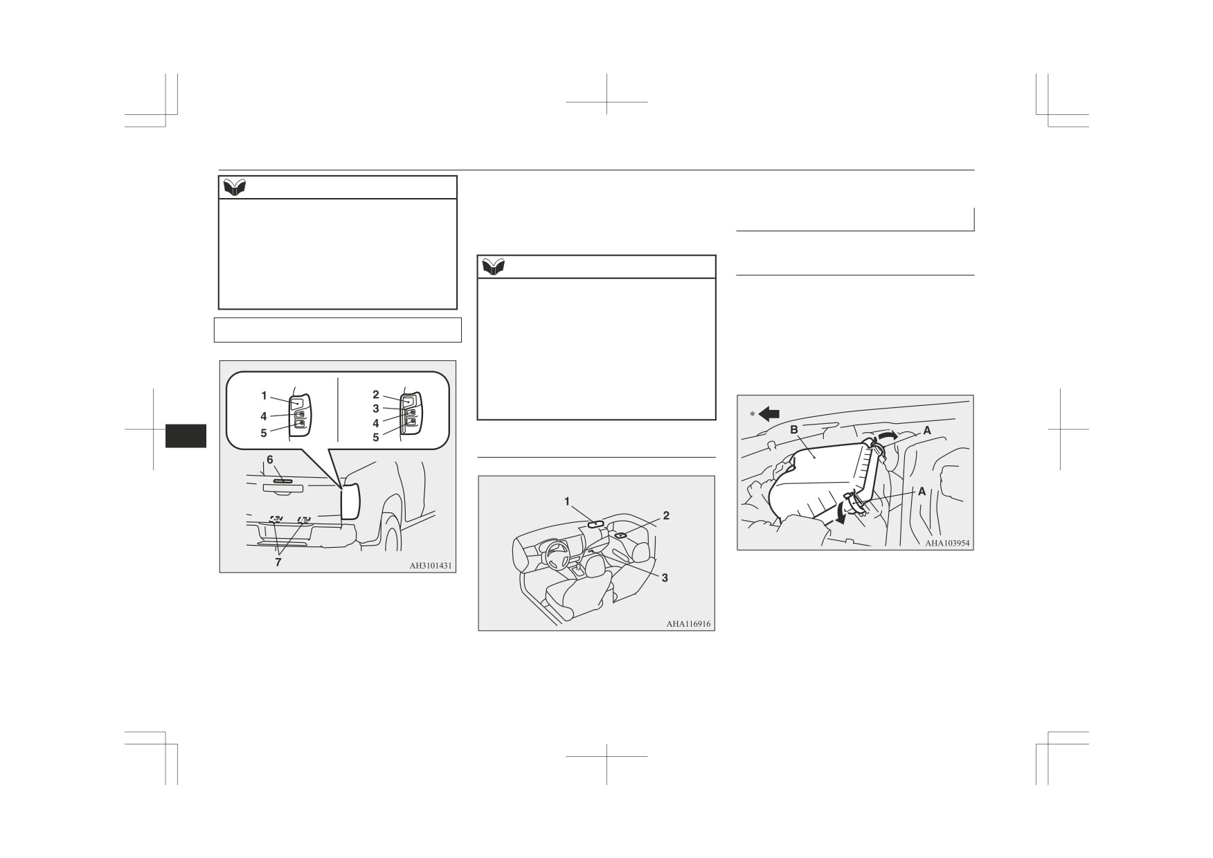
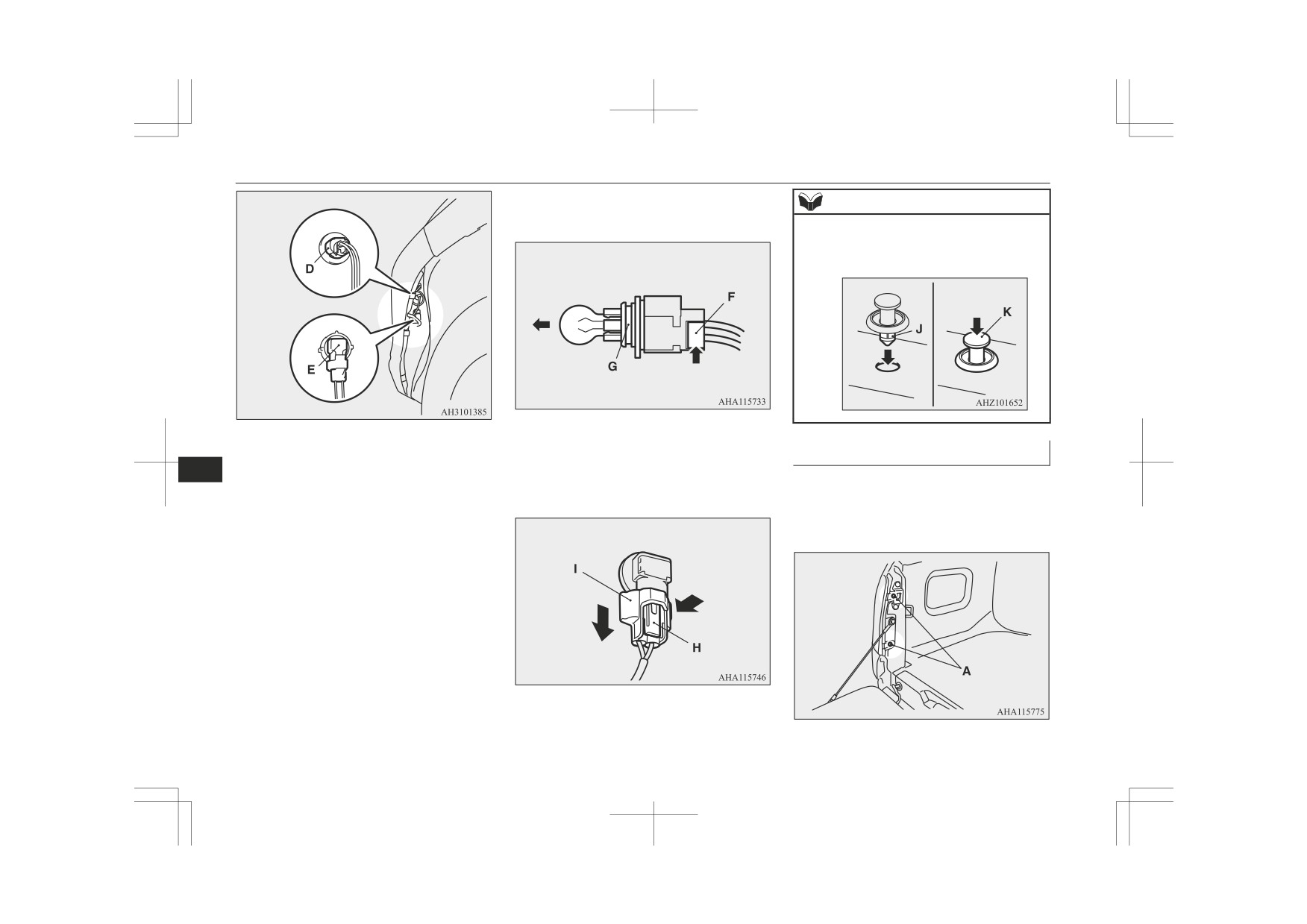
Bulb location and capacity
being turned off.
When replacing a bulb, wait for it to cool
sufficiently before touching it. You could
CAUTION
otherwise be burnt.
z
Handle halogen lamp bulbs with care. The
z When replacing a bulb, be sure to use a new
10
gas inside halogen lamp bulbs is highly pres-
bulb of the same type, wattage and colour. If
surized, so dropping, knocking, or scratching
you install a different bulb, the bulb could
Do not install commercially available LED-
malfunction or fail to come on and could
a halogen lamp bulb can cause it to shatter.
z
type bulbs.
lead to a vehicle fire.
Commercially available LED-type bulbs
could adversely affect the operation of the
vehicle, such as by preventing the lamps and
other vehicle equipment from operating
properly.
NOTE
z
If you are unsure of how to carry out the
work as required, we recommend you to
consult a specialist.
z
Be careful not to scratch the vehicle body
when removing a lamp and lens.
10-24
Maintenance

Replacement of lamp bulbs
Outside
NOTE
7. Front fog lamps*: 35 W (H8)
z It is not possible to repair or replace only the
Front
Codes in parentheses indicate bulb types.
bulb of each side turn-signal lamp (on fend-
Halogen headlamps type A
er).
For repair and replacement, contact a
NOTE
MITSUBISHI MOTORS Authorized Serv-
ice Point when the lamp needs to be repaired
z The side turn-signal lamps use an LED in-
or replaced.
stead of the bulb.
If you need to repair or replace these lamps,
z The side turn-signal lamps (on outside rear-
view mirror) use an LED instead of the bulb.
contact a MITSUBISHI MOTORS Author-
If you need to repair or replace these lamps,
ized Service Point.
contact a MITSUBISHI MOTORS Author-
ized Service Point.
LED headlamps type
Halogen headlamps type B
10
1. Position lamps: 5 W (W5W)
2. Headlamps, high-beam: 60 W (HB3)
3. Headlamps, low beam: 55 W (H11)
4. Side turn-signal lamps (on fender)*: 5W
5. Side turn-signal lamps (on outside rear-
view mirror)*: −
6. Front turn-signal lamps: 21 W (PY21W)
7. Type 1
Front fog lamps*: 35 W (H8)
1. Position lamps/Daytime running lamps:
-
Daytime running lamps*: 13 W (P13W)
1. Position lamps: 5 W (W5W)
2. Headlamps, high/low beam: -
Type 2
2. Headlamps, high-beam: 60 W (HB3)
3. Side turn-signal lamps: -
Daytime running lamps*: 13 W (P13W)
3. Headlamps, low beam: 55 W (H11)
4. Front turn-signal lamps: 21 W (PY21W)
4. Side turn-signal lamps: -
5. Front fog lamps: 35 W (H8)
Codes in parentheses indicate bulb types.
5. Front turn-signal lamps: 21 W (PY21W)
6. Daytime running lamps: 13 W (P13W)
Codes in parentheses indicate bulb types.
Maintenance
10-25
Replacement of lamp bulbs
6. High-mounted stop lamp: -
3. Glove box lamp: 1.4 W
NOTE
7. Licence plate lamps: 5 W (W5W)
z The following lamps use an LED instead of
Headlamps
the bulb. If you need to repair or replace
Codes in parentheses indicate bulb types.
these lamps, contact a MITSUBISHI
MOTORS Authorized Service Point.
Vehicles with halogen head-
• Headlamps
NOTE
lamps type A or type B
• Position lamps/Daytime running lamps
z The following lamps use an LED instead of
[Low beam]
• Side turn-signal lamps
the bulb. If you need to repair or replace
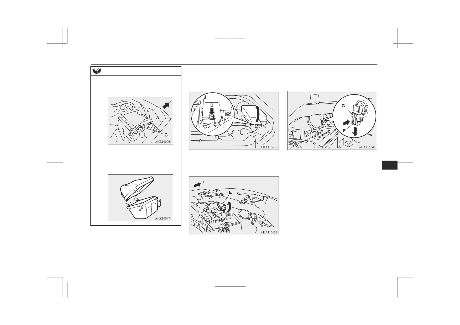
1. When replacing the bulb on the right
these lamps, contact a MITSUBISHI
side of the vehicle, remove the clamps
Rear
MOTORS Authorized Service Point.
(A) of the air cleaner filter and move the
• Tail and stop lamps
upper cover (B) towards the rear of the
• Stop lamps
vehicle.
Type 1
Type 2
• Tail lamps
• Rear fog lamp (driver’s side)
• High-mounted stop lamp
10
Inside
*: Front of the vehicle
1. Tail and stop lamps: -
2. Stop lamps: -
3. Tail lamps: -
4. Rear turn-signal lamps: 21 W (PY21W)
1. Front room & map lamps: 7.5 W
5.Rear fog lamp (driver’s side)*: -
2. Rear room lamp: 8 W
Reversing lamps: 18 W (W16W)
10-26
Maintenance
Replacement of lamp bulbs
2. When replacing the bulb on the left side
4. While holding down the tab (F), pull out
NOTE
of the vehicle, remove the fuse block
the socket (G) from the bulb, and turn
z When moving the upper cover towards the
cover with pushing the tab (D).
the bulb anticlockwise to remove it.
rear of the vehicle, remove the harness from
the air cleaner hooks (C).
*: Front of the vehicle
z After replacing the bulb, make sure that the
hinges at the front of the vehicle are firmly
3. Turn the cover (E) anticlockwise to re-
5. To install the bulb, perform the removal
set.
move it.
steps in reverse.
10
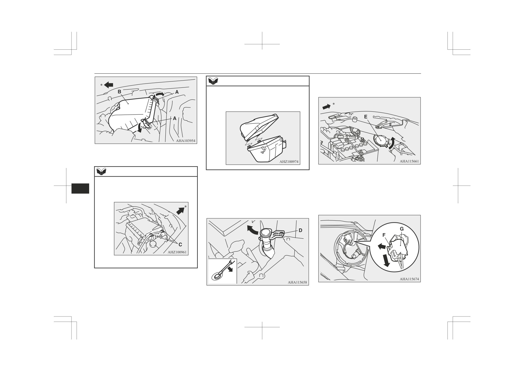
[High-beam]
1. When replacing the bulb on the right
side of the vehicle, remove the clamps
(A) of the air cleaner filter and move the
upper cover (B) towards the rear of the
vehicle.
*: Front of the vehicle
Maintenance
10-27
Replacement of lamp bulbs
3. Turn the cover (E) anticlockwise to re-
NOTE
move it.
z After replacing the bulb, make sure that the
hinges at the front of the vehicle are firmly
set.
*: Front of the vehicle
NOTE
*: Front of the vehicle
2. When replacing the bulb on the left side
z When moving the upper cover towards the
rear of the vehicle, remove the harness from
of the vehicle, remove the clip (D) hold-
10
4. While pulling up the tab (F), pull out the
the air cleaner hooks (C).
ing down the washer tank spout and
socket (G) from the bulb, and turn the
move the spout towards the rear of the
bulb anticlockwise to remove it.
vehicle.
*: Front of the vehicle
10-28
Maintenance

Replacement of lamp bulbs
5. To install the bulb, perform the removal
2. When replacing the bulb on the left side
NOTE
steps in reserve.
of the vehicle, remove the clip (D) hold-
z
When moving the upper cover towards the
ing down the washer tank spout and
rear of the vehicle, remove the harness from
move the spout towards the rear of the
Position lamps
the air cleaner hooks (C).
vehicle.
Vehicles with halogen head-
lamps type A or type B
1. When replacing the bulb on the right
side of the vehicle, remove the clamps
(A) of the air cleaner filter and move the
upper cover (B) towards the rear of the
vehicle.
*: Front of the vehicle
z
After replacing the bulb, make sure that the
hinges at the front of the vehicle are firmly
set.
10
3. Turn the cover (E) anticlockwise to re-
move it.
*: Front of the vehicle
*: Front of the vehicle
Maintenance
10-29
Replacement of lamp bulbs
4. Turn the bulb socket (F) anticlockwise to
4. To install the bulb, perform the removal
remove it. And remove the bulb from the
steps in reverse.
socket by pulling out.
NOTE
z When refitting the clip (B), first insert part
(E) of the clip into the hole and then press
part (F) into it.
*: Front of the vehicle
3. Turn the bulb socket (D) anticlockwise
to remove it. And remove the bulb from
5. To install the bulb, perform the removal
the socket by turning it anticlockwise
10
steps in reverse.
while pressing in.
Front fog lamps* / Daytime
Front turn-signal lamps
running lamps*
1. To create enough work space, turn the
steering wheel all the way in the direc-
Vehicles with halogen head-
tion opposite to the side you wish to re-
lamps type A
place.
2. Remove the 3 bolts (A) and 1 clip (B),
1. To create enough work space, turn the
and then pull back the splash shield (C).
steering wheel all the way in the direc-
tion opposite to the side you wish to re-
place.
2. Remove the 3 bolts (A) and 1 clip (B),
and then pull back the splash shield (C).
10-30
Maintenance

Replacement of lamp bulbs
4. While holding down the tab (F), pull out
Vehicles with halogen head-
the socket (G) from the bulb, and turn
lamps type B or LED head-
the bulb anticlockwise to remove it.
lamps
1. To create enough work space, turn the
Front fog lamp
Daytime running lamp
steering wheel all the way in the direc-
tion opposite to the side you wish to re-
place.
2. Remove the 3 bolts (A) and 1 clip (B),
and then pull back the splash shield (C).
*: Front of the vehicle
3. Confirm the position of the bulb to be
replaced.
5. To install the bulb, perform the removal
steps in reverse.
10
Type 1
Type 2
NOTE
z When refitting the clip (B), first insert part
(H) of the clip into the hole and then press
part (I) into it.
*: Front of the vehicle
3. Confirm the position of the bulb to be
replaced.
D- Front fog lamp
E- Daytime running lamp
Maintenance
10-31
Replacement of lamp bulbs
(F), pull out the bulb (G) from the sock-
NOTE
et.
z When refitting the clip (B), first insert part
(J) of the clip into the hole and then press
part (K) into it.
[Front fog lamp]
D- Daytime running lamp
Rear combination lamps
While holding down the tab (H), pull out
E- Front fog lamp
10
the socket (I) from the bulb, and turn the
1. Open the rear gate.
bulb anticlockwise to remove it.
(Refer to “Rear gate” on page 3-20.)
4. [Daytime running lamp]
2. Remove the screws (A) that hold the
Turn the socket (D) anticlockwise to re-
lamp unit.
move it, and while holding down the tab
5. To install the bulb, perform the removal
steps in reverse.
10-32
Maintenance

Replacement of lamp bulbs
3. Move the lamp unit towards the rear of
D-
Reversing lamp
2. Remove the socket and bulb assembly
the vehicle and remove the clips (B).
Remove the bulb by pulling it
together by turning it anticlockwise, and
out.
then remove the bulb by pulling it out.
5. To install the bulb, perform the removal
steps in reverse.
Licence plate lamps
1. Insert a straight blade (or minus) screw-
driver into the lamp assembly and pry
gently to remove it.
4. Remove each socket and bulb assembly
by turning it anticlockwise.
3. To install the bulb, perform the removal
steps in reverse.
10
NOTE
z Wrap a piece of cloth around the tip of the
screwdriver in order to avoid scratching the
lens and the body.
C-
Rear turn-signal lamp
Remove the bulb by pulling it
out.
Maintenance
10-33
Replacement of lamp bulbs
Vehicles with ERA-GLONASS
Vehicles without ERA-GLONASS
NOTE
z When mounting the lamp unit, put the hook
(A) on the right side of the lamp unit into the
body first.
Vehicles with ERA-GLONASS
NOTE
Front room & map lamps
z Wrap a piece of cloth around the tip of the
screwdriver in order to avoid scratching the
10
1. Insert a straight blade (or minus) screw-
lens.
driver into the notch of the lens and pry
gently to remove it.
2. To install the bulb, perform the removal
Remove the bulb from the lamp holder.
steps in reverse.
Vehicles without ERA-GLONASS
NOTE
z When installing the lens, align the tab (A) on
the lens with the holes on the vehicle side.
Rear room lamp
1. Insert a straight blade (or minus) screw-
driver into the notch of the lens and pry
10-34
Maintenance

Replacement of lamp bulbs
gently to remove it. Remove the bulb
from the lamp holder.
Glove box lamp
Have the glove box lamp bulb replaced at a
MITSUBISHI MOTORS Authorized Service
NOTE
Point.
z Wrap a piece of cloth around the tip of the
10
screwdriver in order to avoid scratching the
lens.
2. To install the bulb, perform the removal
steps in reverse.
NOTE
z When installing the lens, align the 2 tabs on
the lens with the holes on the vehicle side.
Maintenance
10-35
Specifications
Vehicle labeling
11-02
Vehicle dimensions
11-04
Vehicle performance
11-08
Vehicle weight
11-08
Engine specifications
11-12
Electrical system
11-12
Tyres and wheels
11-13
Fuel consumption
11-13
Capacity
11-15
11
Vehicle labeling
Vehicle labeling
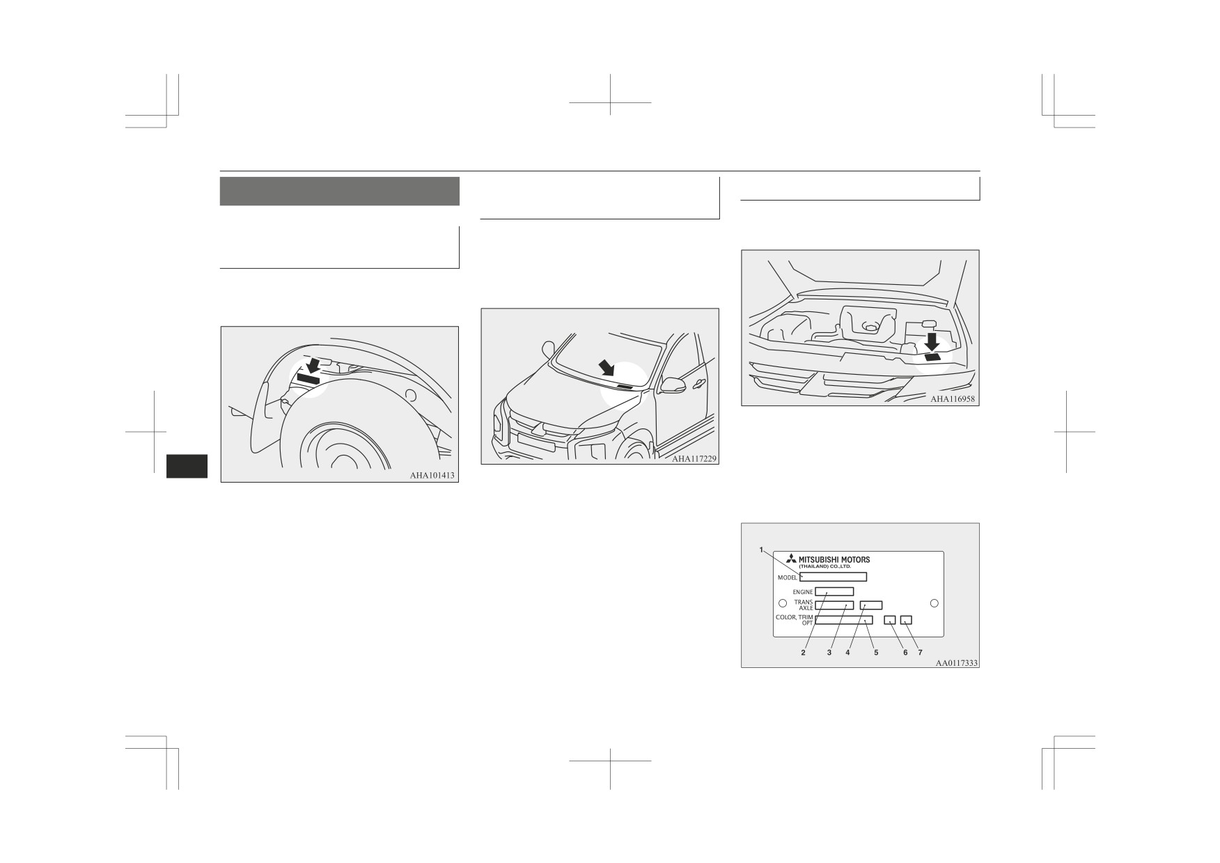
Vehicle identification number
Vehicle information code plate
plate (RHD vehicles only)
The vehicle information code plate is located
as shown in the illustration.
Vehicle Identification Number:
The vehicle identification number is stamped
on the plate riveted to the left front corner of
(VIN)
the vehicle body. It is visible from outside of
The vehicle identification number is stamped
the vehicle through the windscreen.
as shown in the illustration.
The plate shows model code, engine model,
transmission model and body colour code,
11
etc.
Please use this number when ordering re-
placement parts.
11-02
Specifications

Vehicle labeling
1- Model code
2- Engine model code
3- Transmission model code
4- Final gear ratio
5- Body colour code
6- Interior code
7- Option code
Engine model/number
The engine model and number are stamped
on the engine cylinder block as shown in the
illustrations.
11
Specifications
11-03
Vehicle dimensions
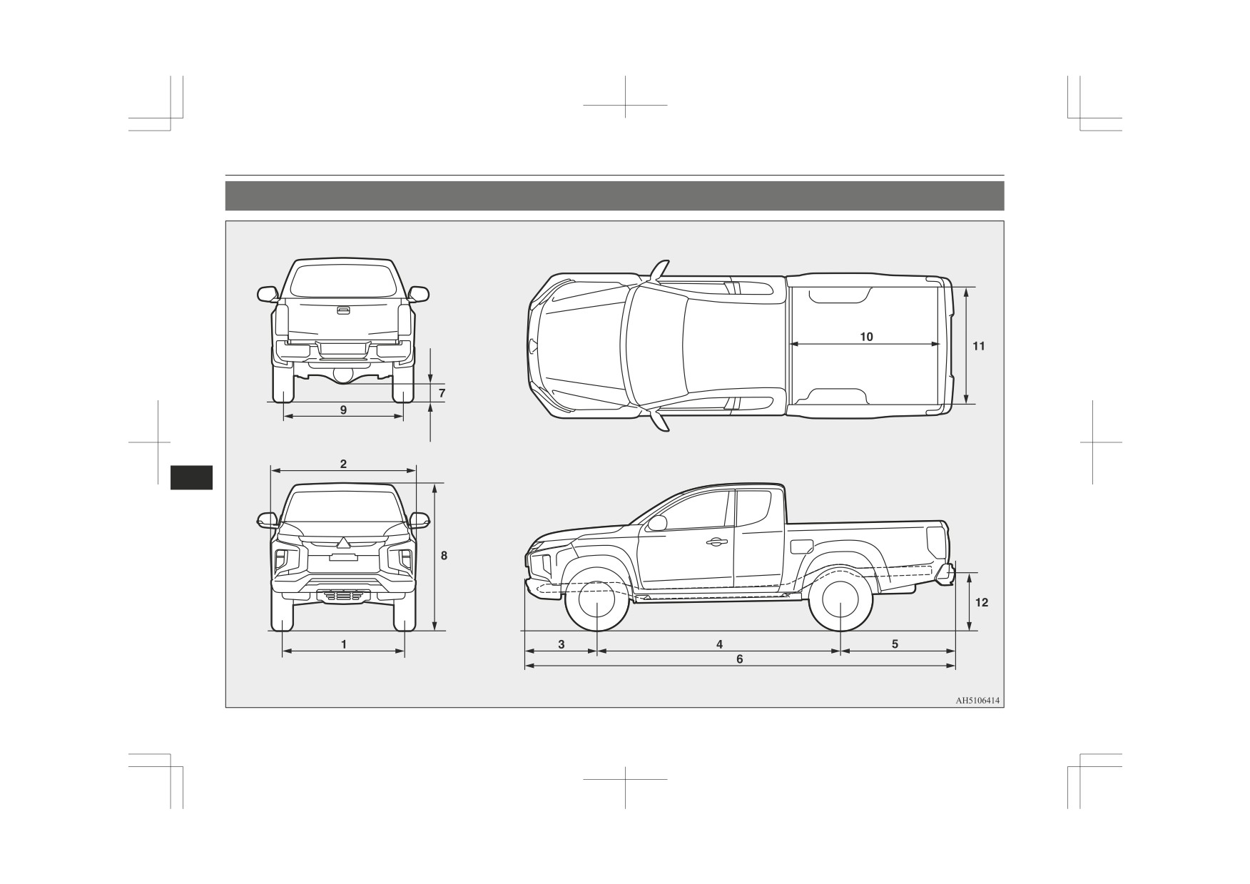
Vehicle dimensions
Club Cab
11
11-04
Specifications
Vehicle dimensions
Club cab
1
Front track
1,520 mm
2
Overall width
1,815 mm
3
Front overhang
885 mm
4
Wheel base
3,000 mm
Without rear bumper
1,330 mm
5
Rear overhang
With rear bumper
1,410 mm
Without rear bumper
5,215 mm
6
Overall length
With rear bumper
5,295 mm
7
Ground clearance (unladen)
205 mm
8
Overall height (unladen)
1,780 mm
9
Rear track
1,515 mm
10
Cargo bed length
1,850 mm
11
11
Cargo bed width
1,470 mm
12
Cargo bed height
850 mm
Minimum turning radius
Body
6.3 m
Wheel
5.9 m
Specifications
11-05
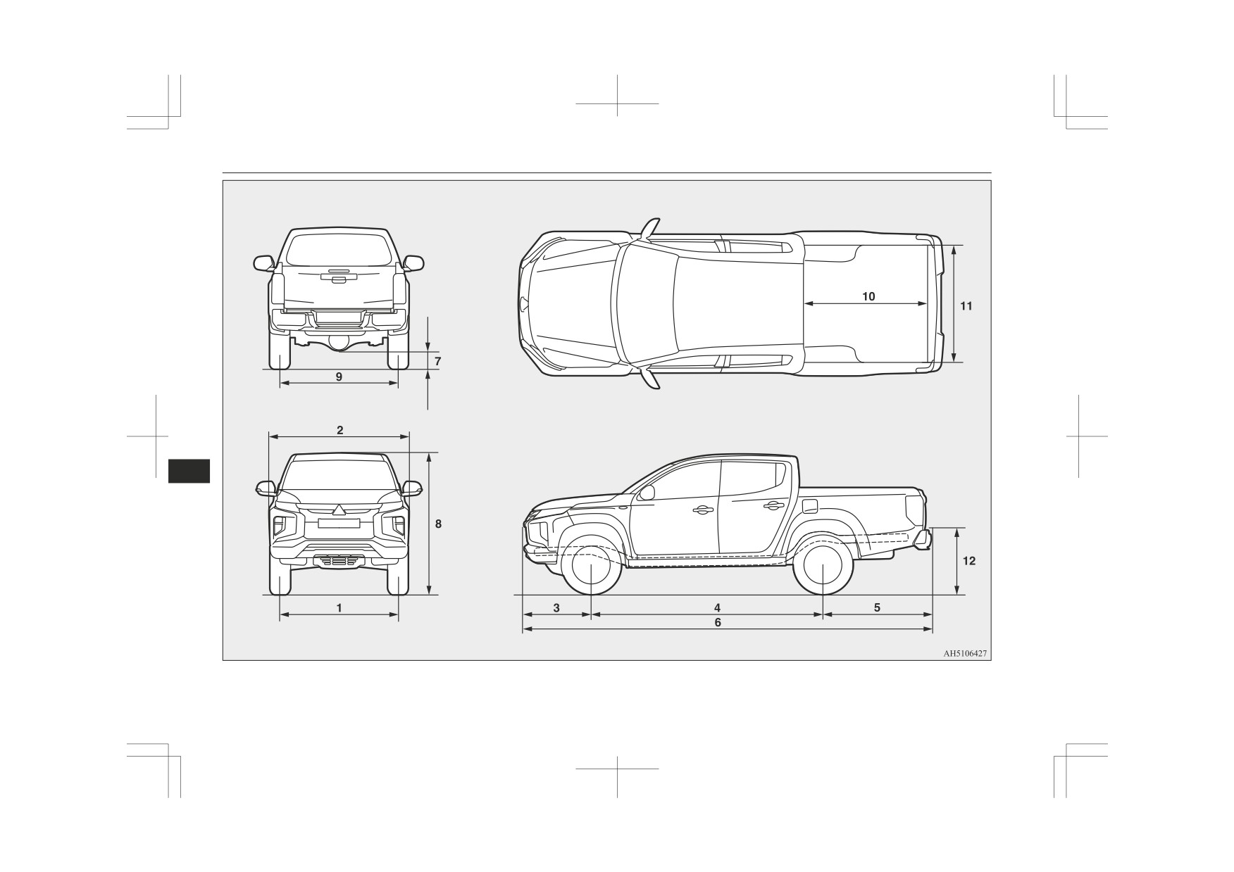
Vehicle dimensions
Double cab
11
11-06
Specifications
Vehicle dimensions
Double cab
1
Front track
1,520 mm
2
Overall width
1,815 mm
3
Front overhang
885 mm
4
Wheel base
3,000 mm
Without rear bumper
1,340 mm
5
Rear overhang
With rear bumper
1,420 mm
Without rear bumper
5,225 mm
6
Overall length
With rear bumper
5,305 mm
7
Ground clearance (unladen)
205 mm*1, 220 mm*2, 200 mm*3
8
Overall height (unladen)
1,780 mm*1, 1,795 mm*2, 1,775 mm*3
9
Rear track
1,515 mm
10
Cargo bed length
1,520 mm
11
11
Cargo bed width
1,470 mm
12
Cargo bed height
850 mm*1, 865 mm*2, 845 mm*3
*1: Vehicles with 245/70R16 111S RF tyre
*2: Vehicles with 265/60R18 110H tyre
*3: Vehicles with 205R16C 8PR 110/108R tyre
Minimum turning radius
Body
6.3 m
Wheel
5.9 m
Specifications
11-07
Vehicle performance
Vehicle performance
4N14
4N15
Item
M/T
M/T
A/T
A/T
ES4
SS4
171 km/h,
Maximum speed
174 km/h
171 km/h
169 km/h (105 mph)
173 km/h
177 km/h(110 mph)*
*: Vehicles with high power engine
Vehicle weight
Club cab
LHD
Item
RHD
11
Easy Select 4WD
Super Select 4WD II
Without optional parts
1,950 kg
1,990 kg
1,950 kg
Kerb weight
With full optional parts
1,980 kg
2,035 kg
1,970 kg
Maximum gross vehicle weight
3,110 kg
Front
1,360 kg
Maximum axle weight
Rear
2,030 kg
With brake
3,000 kg
Maximum towable weight
Without brake
750 kg
Maximum trailer-nose weight
120 kg
*: Vehicles equipped with rear seatless option
11-08
Specifications

Vehicle weight
LHD
Item
RHD
Easy Select 4WD
Super Select 4WD II
Maximum gross combination weight
6,080 kg
Maximum permissible weight of the coupling device
34 kg
Seating capacity
4 persons, 2 persons*
*: Vehicles equipped with rear seatless option
NOTE
z Trailer specifications indicate the manufacturer’s recommendation.
Double cab
2WD Hi-Rider
Item
M/T
A/T
11
Without optional parts
1,895 kg
1,900 kg
Kerb weight
With full optional parts
1,915 kg
1,920 kg
Maximum gross vehicle weight
3,000 kg
Front
1,360 kg
Maximum axle weight
Rear
2,030 kg
With brake
2,700 kg
Maximum towable weight
Without brake
750 kg
Maximum trailer-nose weight
110 kg
Maximum gross combination weight
5,650 kg
Maximum permissible weight of the coupling device
34 kg
Specifications
11-09

Vehicle weight
2WD Hi-Rider
Item
M/T
A/T
Maximum roof load
80 kg
Seating capacity
5 persons
NOTE
z Trailer specifications indicate the manufacturer’s recommendation.
4WD
M/T
A/T
Item
LHD
RHD
LHD
Easy Select
Super Select
Easy Select
Super Select
Easy Select
Super Select
RHD
RHD 4WD
4WD II
4WD
4WD II
4WD
4WD II
2,035 kg,
11
2,000 kg,
2,030 kg,
Without optional parts
2,000 kg
2,030 kg
2,005 kg
1,925 kg*1,
2,035 kg
1,895 kg*1
1,925 kg*1
1,930 kg*2
Kerb weight
2,075 kg,
2,020 kg,
2,070 kg,
With full optional parts
2,020 kg
2,070 kg
2,025 kg
1,995 kg*1,
2,075 kg
1,935 kg*1
1,990 kg*1
1,995 kg*2
Maximum gross vehicle weight
2,850 kg*1, *2 3,110 kg
Maximum axle weight
Front
1,260 kg*1, *2, 1,360 kg
*1: Vehicles for Russia and Ukraine
*2: Vehicles with high power engine
*3: Except for vehicles for Russia and Ukraine
11-10
Specifications