Mitsubishi Outlander XL. Manual - part 989
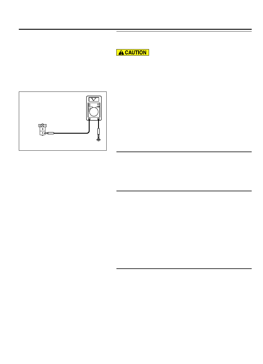
STEP 4. Check the battery power supply circuit to the
headlight relay (LOW). Measure the voltage at headlight
relay (LOW) connector A-28X.
The top and bottom of the headlight relay (LOW) are difficult
to identify. Prior to inspection, confirm the triangle mark on
the relay box.
(1)
Disconnect headlight relay (LOW) connector A-28X and
measure the voltage available at the relay box side of the
connector.
ZC5010400051
Relay box side: A-28X
(2)
Measure the voltage between terminal 4 and ground.
⦆
The voltage should measure approximately 12 volts
(battery positive voltage).
Q:Is the measured voltage approximately 12 volts (battery
positive voltage)?
YES:
Go to Step 5.
NO:
Go to Step 7.
STEP 5. Check ETACS-ECU connector C-312 for loose,
corroded or damaged terminals, or terminals pushed back
in the connector.
Q:Is ETACS-ECU connector C-312 in good condition?
YES:
Go to Step 6.
NO:
Repair the damaged parts.
STEP 6. Check the wiring harness between headlight relay
(LOW) connector A-28X (terminal 1) and ETACS-ECU
connector C-312 (terminal 6).
⦆
Check the ground wires for open circuit.
Q:Is the wiring harness between headlight relay (LOW)
connector A-28X (terminal 1) and ETACS-ECU connector
C-312 (terminal 6) in good condition?
YES:
Go to Step 8.
NO:
The wiring harness may be damaged or the connector
(s) may have loose, corroded or damaged terminals, or
terminals pushed back in the connector. Repair the wiring
harness as necessary. Verify that the low-beam headlights
illuminate normally.
STEP 7. Check the wiring harness between headlight relay
(LOW) connector A-28X (terminal 4) and the fusible link (36).
⦆
Check the power supply line for open circuit.
Q:Is the wiring harness between headlight relay (LOW)
connector A-28X (terminal 4) and fusible link (36) in good
condition?
YES:
Go to Step 8.
NO:
The wiring harness may be damaged or the connector
(s) may have loose, corroded or damaged terminals, or
terminals pushed back in the connector. Repair the wiring
LIGHTING
54Ac-29
DIAGNOSIS