Mitsubishi Outlander XL. Manual - part 969
STEP 1. Using scan tool MB991958, diagnose the CAN bus
line
ZC501967
AC404789
ZC5019680000
MB991824
MB991827
MB991910
Data link
connector
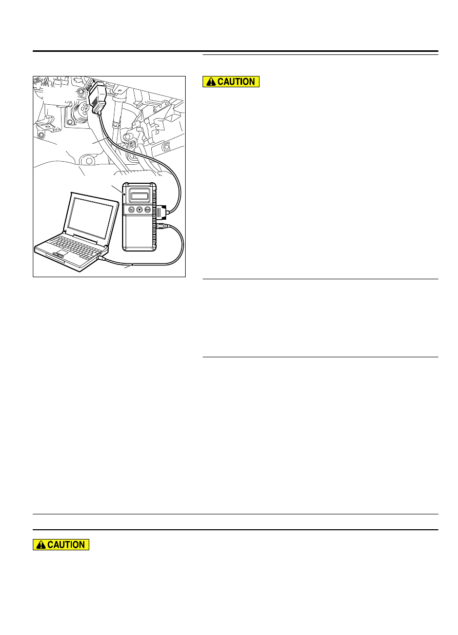
To prevent damage to scan tool MB991958, always turn the
ignition switch to the "LOCK" (OFF) position before
connecting or disconnecting scan tool MB991958.
(1)
Connect scan tool MB991958. Refer to "How to connect the
Scan Tool (M.U.T.-III) P.54Ab-5."
(2)
Turn the ignition switch to the "ON" position.
(3)
Diagnose the CAN bus line.
(4)
Turn the ignition switch to the "LOCK" (OFF) position.
Q:Is the CAN bus line found to be normal?
YES:
Go to Step 2.
NO:
Repair the CAN bus line. (Refer to GROUP 54D,
STEP 2. Using scan tool MB991958, read the SRS-ECU
diagnostic trouble code
Check again if the DTC is set to the SRS-ECU.
Q:Is the DTC set?
YES:
Troubleshoot the SRS (Refer to GROUP 52B,
NO:
Go to Step 3.
STEP 3. Recheck for diagnostic trouble code.
Check again if the DTC is set to the combination meter.
(1)
Erase the DTC.
(2)
Turn the ignition switch from "LOCK" (OFF) position to "ON"
position.
(3)
Check if DTC is set.
(4)
Turn the ignition switch to the "LOCK" (OFF) position.
Q:Is the DTC set?
YES:
Replace the combination meter.
NO:
The trouble can be an intermittent malfunction (Refer
to GROUP 00 - How to use Troubleshooting/inspection
Service Points - How to Cope with Intermittent
Malfunction P.00-15).
DTC U0154: Occupant classification-ECU CAN timeout
M15410100105USA0000010000
⦆
If DTC U0154 is set, be sure to diagnose the CAN
bus line.
⦆
When replacing the ECU, always check that the
communication circuit is normal.
COMBINATION METER
54Ab-29
DIAGNOSIS