Mitsubishi Outlander XL. Manual - part 963
Tool
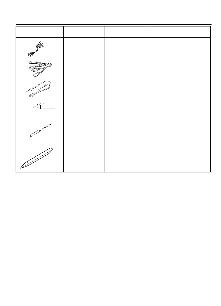
Tool number and
name
Supersession
Application
YB9912230000
Do not use
a
b
c
d
MB991223
a.
MB991219
b.
MB991220
c.
MB991221
d.
MB991222
Harness set
a.
Test harness
b.
LED harness
c.
LED
harness
adaptor
d.
Probe
General service tools Continuity check and voltage
measurement at harness wire or
connector for loose, corroded or
damaged terminals, or terminals
pushed back in the connector.
a.
Connector
pin
contact
pressure inspection
b.
Power circuit inspection
c.
Power circuit inspection
d.
Commercial tester connection
MB992006
MB992006
Extra fine probe
-
Making voltage and resistance
measurement
during
troubleshooting
MB990784
MB990784
Ornament remover
General service tool
Removal of switch, trim, etc.
DIAGNOSIS
STANDARD FLOW OF DIAGNOSTIC
TROUBLESHOOTING
M15410100086USA0000010000
Refer to GROUP 00, Contents of troubleshooting P.00-6.
DIAGNOSTIC FUNCTION
M15410100006USA0000010000
HOW TO CONNECT THE SCAN TOOL (M.U.T.-III)
Required Special Tools:
⦆
MB991958: Scan Tool (M.U.T.-III Sub Assembly)
⦆
MB991824: Vehicles Communication Interface (V.C.I.)
⦆
MB991827: M.U.T.-III USB Cable
⦆
MB991910: M.U.T.-III Main Harness A (Vehicles with
CAN communication system)
COMBINATION METER
54Ab-5
DIAGNOSIS