Mitsubishi Outlander XL. Manual - part 911


  Index      Mitsubishi     Mitsubishi Outlander XL - service repair manual 2007 year


Search            copyright infringement  


Content   ..  909  910  911  912   ..


Mitsubishi Outlander XL. Manual - part 911


STEP 2. Recheck for diagnostic trouble code.

ZC501967

AC404789

ZC5019680000

MB991824

MB991827

MB991910

Data link

connector

Check again if the DTC is set.

(1)

Erase the DTC.

(2)

Turn the ignition switch to "ON" position.

(3)

Check if the DTC is set.

(4)

Turn the ignition switch to the "LOCK" (OFF) position.

Q:Is the DTC set?

YES:

 Go to Step 3.

NO:

 There is an intermittent malfunction such as poor

engaged connector(s) or open circuit (Refer to GROUP 00,
How to Cope with Intermittent Malfunction P.00-15).

STEP 3. Check SRS-ECU connector C-27 and side-airbag
module (LH) connector D-29. (Using scan tool MB991958,
read the diagnostic trouble code.)

(1)

Disconnect the negative battery terminal.

(2)

Disconnect connectors C-27 and D-29, and then reconnect
them.

(3)

Connect the negative battery terminal.

(4)

Erase the diagnostic trouble code memory, and check the
diagnostic trouble code.

Q:Is DTC B1C2A out put?

YES:

 Go to Step 4.

NO:

 The procedure is complete. It is assumed that DTC

B1C2A set because connector C-27 or D-29 was engaged
improperly.

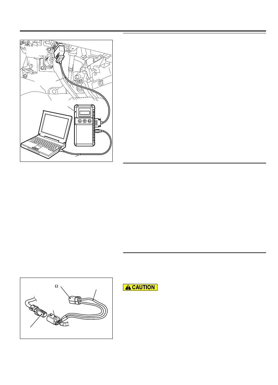
STEP 4. Check the side-airbag module (LH). (Using scan
tool MB991958, read the diagnostic trouble code.)

(1)

Disconnect the negative battery terminal.

(2)

Disconnect the side-airbag module (LH) connector D-29.

ZC600211

D-29 

Side-airbag  

module (LH) connector

D-29  
Harness side  
connector

0002

MB991865 
(Dummy resistor: 3    )

MB991866  

(Resistor harness)

(3)

Connect special tool MB991865 to special tool MB991866.

Do not insert a test probe into the terminal from its front side
directly,  as  the  connector  contact  pressure  may  be
weakened.

(4)

Insert  special  tool  MB991866  into  the  D-29  harness  side
connector by backprobing.

(5)

Connect the negative battery terminal.

(6)

Erase  diagnostic  trouble  code  memory,  and  check  the
diagnostic trouble code.

SUPPLEMENTAL RESTRAINT SYSTEM (SRS)

52B-175

SRS AIR BAG DIAGNOSIS

Q:Is DTC B1C2A set?

YES:

 Go to Step 5.

NO:

 Replace the seatback frame of the front seat (LH).

Then go to Step 7.

STEP 5. Check the side-airbag module (LH) circuit. Measure
the resistance at the SRS-ECU connector C-27.

(1)

Disconnect SRS-ECU connector C-27.

To  prevent  the  air  bag  from  deploying  unintentionally,
disconnect the side-airbag module (LH) connector D-29 to
short the squib circuit.

(2)

Disconnect  left  hand  side-airbag  module  (LH)  connector
D-29.

ZC6021620002

A

A

C-27 Harness side 
connector (front view)

Section
A - A

Cable tie

Short spring

4 mm or more

Terminal

Insert an insulator such as a cable tie to a depth of 4mm
(0.16 inch) or more, otherwise the short spring will not be
released.

(3)

Insert a cable tie [3 mm (0.12 inch) wide, 0.5 mm (0.02 inch)
thick]  between  terminals  31,  32  and  the  short  spring  to
release the short spring.

ZC5007880035

C-27 Harness side 
connector (front view)

Do not insert a test probe into the terminal from its front side
directly,  as  the  connector  contact  pressure  may  be
weakened.

(4)

Check for continuity between C-27 harness side connector
terminals 31 and 32.
It should be an open circuit.

Q:Is the circuit normal?

YES:

 Go to Step 6.

NO:

 Erase the diagnostic trouble code memory, and check

the diagnostic trouble code. If DTC B1C2A sets, replace
the SRS-ECU. (Refer to P.52B-326). Then go to Step 7.

STEP 6. Check the harness wires for short circuit between
SRS-ECU connector C-27 (terminal No.31 and 32) and side-
airbag module (LH) connector D-29 (terminal No.2 and 1).

Q:Are the harness wires between SRS-ECU connector C-27

(terminal  No.31  and  32)  and  side-airbag  module  (LH)

connector D-29 (terminal No.2 and 1) in good condition?

YES:

 Go to Step 7.

NO:

 Replace the harness wires between SRS-ECU connector

C-27 and side-airbag module (LH) connector D-29. Then go
to Step 7.

52B-176

SUPPLEMENTAL RESTRAINT SYSTEM (SRS)

SRS AIR BAG DIAGNOSIS

STEP 7. Recheck for diagnostic trouble code.

ZC501967

AC404789

ZC5019680000

MB991824

MB991827

MB991910

Data link

connector

Check again if the DTC is set.

(1)

Erase the DTC.

(2)

Turn the ignition switch to the "ON" position.

(3)

Check if the DTC is set.

(4)

Turn the ignition switch to the "LOCK" (OFF) position.

Q:Is DTC B1C2A set?

YES:

 Return to Step 1.

NO:

 The procedure is complete.

SUPPLEMENTAL RESTRAINT SYSTEM (SRS)

52B-177

SRS AIR BAG DIAGNOSIS

DTC B1C2B Side-airbag Module (RH) (Squib) System (Shorted to Squib Circuit Ground)

M15204000951USA0000010000

CONNECTOR
LOCK SWITCH

Side-airbag Module (Squib) (RH) Circuit

CONNECTOR
LOCK SWITCH

SIDE-AIRBAG
MODULE
(SQUIB) (RH)

SRS-ECU

: CONNECTOR COUPLED : ON
  CONNECTOR UNCOUPLED : OFF

NOTE

ZC600876

Connector: C-27

C-27 (Y)

0025

ZC600879

Connector: D-31

D-31 (Y)

0010


If  DTC  B1C2B  is  set  in  the  SRS-ECU,  always
diagnose the CAN bus lines.

CIRCUIT OPERATION

The SRS-ECU judges how severe a collision is by
detecting  signals  from  the  side  impact  sensor
installed on the lower side of the center pillar. If the
impact is over a predetermined level, the SRS-ECU

sends  an  ignition  signal.  At  this  time,  if  the  side-
airbag safing G-sensor is on, the SRS side-airbag
will inflate.

The ignition signal is input to the side-airbag module
to inflate the side-airbag.

52B-178

SUPPLEMENTAL RESTRAINT SYSTEM (SRS)

SRS AIR BAG DIAGNOSIS


Content   ..  909  910  911  912   ..