Mitsubishi Outlander XL. Manual - part 905
Q:Is either DTC B1B72 or B1B75 set?
YES:
Replace the SRS-ECU (Refer to P.52B-326).
NO:
The procedure is complete.
DTC B1B73: Malfunction of G-sensor Inside Side Impact Sensor (Rear) (LH)
DTC B1B76: Malfunction of G-sensor Inside Side Impact Sensor (Rear) (RH)
M15204000962USA0000010000
If DTC B1B73 or B1B76 is set in the SRS-ECU,
always diagnose the CAN main bus line.
DTC SET CONDITIONS
These DTCs are set if the following conditions are
detected from the analog G-sensor inside the side
impact sensor output:
⦆
Analog G-sensor is not operating.
⦆
Analog G-sensor characteristics are abnormal.
⦆
Analog G-sensor output is abnormal.
TROUBLESHOOTING HINTS
Malfunction of side impact sensor (rear) (LH) (for DTC
B1B73) and impact sensor (rear) (RH) (for DTC
B1B76)
DIAGNOSIS
Required Special Tools:
⦆
MB991958: Scan Tool (M.U.T.-III Sub Assembly)
⦆
MB991824: Vehicle Communication Interface (V.C.I.)
⦆
MB991827: M.U.T.-III USB Cable
⦆
MB991910: M.U.T.-III Main Harness A (Vehicles with
CAN Communication System)
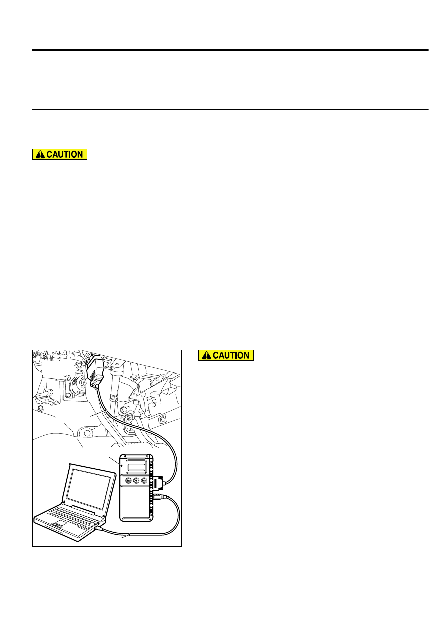
STEP 1. Using scan tool MB991958, diagnose the CAN bus
line.
ZC501967
AC404789
ZC5019680000
MB991824
MB991827
MB991910
Data link
connector
To prevent damage to scan tool MB991958, always turn the
ignition switch to the "LOCK" (OFF) position before
connecting or disconnecting scan tool MB991958.
(1)
Connect scan tool MB991958. Refer to "How to connect the
scan tool P.52B-31."
(2)
Turn the ignition switch to the "ON" position.
(3)
Diagnose the CAN bus line.
(4)
Turn the ignition switch to the "LOCK" (OFF) position.
Q:Is the CAN bus line found to be normal?
YES:
Go to Step 2.
NO:
Repair the CAN bus line (Refer to GROUP 54D,
SUPPLEMENTAL RESTRAINT SYSTEM (SRS)
52B-151
SRS AIR BAG DIAGNOSIS