Mitsubishi Outlander XL. Manual - part 795


  Index      Mitsubishi     Mitsubishi Outlander XL - service repair manual 2007 year


Search            copyright infringement  


Content   ..  793  794  795  796   ..


Mitsubishi Outlander XL. Manual - part 795


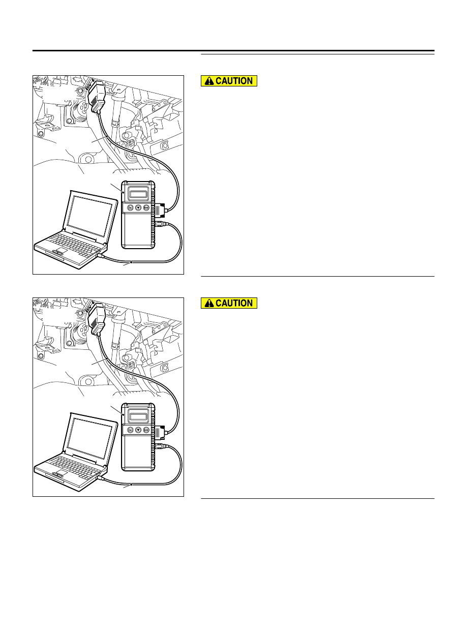
STEP 1. Using scan tool MB991958, read CAN bus the
diagnostic trouble code.

ZC501967

AC404789

ZC5019680000

MB991824

MB991827

MB991910

Data link

connector

To prevent damage to scan tool MB991958, always turn the
ignition  switch  to  the  "LOCK"  (OFF)  position  before
connecting or disconnecting scan tool MB991958.

(1)

Connect scan tool MB991958. Refer to "How to connect scan
tool (M.U.T.-III) P.42B-10."

(2)

Turn the ignition switch to the "ON" position.

(3)

Check whether the CAN bus lines related DTC is set.

(4)

Turn the ignition switch to the "LOCK" (OFF) position.

Q:Is the DTC set?

YES:

 Repair the CAN bus line (Refer to GROUP 54D, CAN bus

diagnostics table P.54D-17).

NO:

 Go to Step 2.

STEP 2. Using scan tool MB991958, read the diagnostic
trouble code.

ZC501967

AC404789

ZC5019680000

MB991824

MB991827

MB991910

Data link

connector

To prevent damage to scan tool MB991958, always turn the
ignition  switch  to  the  "LOCK"  (OFF)  position  before
connecting or disconnecting scan tool MB991958.

(1)

Connect scan tool MB991958. Refer to "How to connect scan
tool (M.U.T.-III) P.42B-10."

(2)

Turn the ignition switch to the "ON" position.

(3)

Check whether the KOS-ECU related DTC is set.

(4)

Turn the ignition switch to the "LOCK" (OFF) position.

Q:Is the DTC set?

YES:

 Diagnose the KOS-ECU. Refer to P.42B-18.

NO:

 Go to Step 3.

STEP 3. Check the central door locking system operation
Check that the central door locking system works normally.

Q:Is the check result normal?

YES:

 Go to Step 4.

KEYLESS OPERATION SYSTEM (KOS)

42B-123

DIAGNOSIS

NO:

 Perform troubleshooting for the central door locking

system (Refer to GROUP 42Ab, Trouble symptom chart P.
42Ab-11).

STEP 4. Check the customize function.
Check that either of the followings other than "ENG strt enable"
or  "Both  disabled"  are  set  for  "KOS  feature"  with  the
customization function.

Both enable

Door Entry enable

Q:Is the check result normal?

YES:

 Go to Step 5.

NO:

 Set either of the followings other than "ENG strt

enable" or "Both disabled" for "KOS feature" with the
customization function (Refer to P.42B-170).

STEP 5. Key reminder switch check.

(1)

Disconnect the C-315 ETACS-ECU connector.

(2)

Measure the resistance at the harness-side connector with
the ignition key removed from the ignition key cylinder.

ZC5007880051

Connector C-315 
(harness side)

(3)

Check  for  continuity  between  the  C-315  ETACS-ECU
connector terminal No. 13 and the ground.

OK: Continuity exists (2 Ω or less)

Q:Is the check result normal?

YES:

 Go to Step 6.

NO:

 Check the C-209 key reminder switch connector, the

C-315 ETACS-ECU connector, the wiring harness between the
C-211 key reminder switch connector (terminal No. 3) and
the C-315 ETACS-ECU connector (terminal No. 13), and
between the C-211 key reminder switch connector (terminal
No. 2) and the ground. If they are normal, replace the key
reminder switch.

STEP 6. Check with another registered keyless operation
key.

Q:Does  the  IG  knob  turn?  (Is  the  keyless  operation  key

recognised?)

YES:

 Replace the keyless operation key with which the IG

knob does not turn (no recognition) and register the ID
codes (Refer to P.42B-163).

NO:

 Go to Step 7.

STEP 7. Check of the troubles.
Operate the lock switch and check that the door can be locked
and unlocked. Also, check that the unlock sensor can lock and
unlock the door.

Q:Is the check result normal?

YES:

 The procedure is complete.

NO:

 Replace KOS-ECU and register the ID codes (Refer

to P.42B-163).

42B-124

KEYLESS OPERATION SYSTEM (KOS)

DIAGNOSIS

INSPECTION PROCEDURE 7: Driver's Door Lock Switch does not Work.

M14209100110USA0000010000

Before replacing the ECU, ensure that the power
supply  circuit,  the  ground  circuit  and  the
communication circuit are normal.

ZC603128

KOS-ECU

LOCK SWITCH 
(FRONT DOOR: LH)

BLA

CK

GREEN -WHITE

BLA

CK

GREEN -WHITE

0000

 Lock switch (Front Door: LH) Circuit

ZC600875

ZC6008750026

C-126

C-102

C-127 (BR)

Connectors: C-102, C-126, C-127

ZC600881

Connector: E-23

E-23 (GR)

0008

PROBABLE CAUSES

Malfunction  of  the  exterior  transmitter  antenna
assembly (driver's side)

Malfunction of the lock switch (front door: LH)

Damaged wiring harness and connectors

Malfunction of the KOS-ECU

KEYLESS OPERATION SYSTEM (KOS)

42B-125

DIAGNOSIS

DIAGNOSTIC PROCEDURE

Required Special Tools:

MB991223: Harness Set

MB992006: Extra Fine Probe

MB991958: Scan Tool (M.U.T.-III Sub Assembly)

MB991824: Vehicle Communication Interface (V.C.I.)

MB991827: M.U.T.-III USB Cable

MB991910: M.U.T.-III Main Harness A

STEP 1. Using scan tool MB991958, read the diagnostic
trouble code.

ZC501967

AC404789

ZC5019680000

MB991824

MB991827

MB991910

Data link

connector

To prevent damage to scan tool MB991958, always turn the
ignition  switch  to  the  "LOCK"  (OFF)  position  before
connecting or disconnecting scan tool MB991958.

(1)

Connect scan tool MB991958. Refer to "How to connect scan
tool (M.U.T.-III) P.42B-10."

(2)

Turn the ignition switch to the "ON" position.

(3)

Check whether the KOS-ECU related DTC is set.

(4)

Turn the ignition switch to the "LOCK" (OFF) position.

Q:Is the DTC set?

YES:

 Diagnose the KOS-ECU. Refer to P.42B-18.

NO:

 Go to Step 2.

STEP 2. Check KOS-ECU connector C-102 and lock switch
(front door: LH) connector E-23 for loose, corroded or
damaged terminals, or terminals pushed back in the
connector.

Q:Are  KOS-ECU  connector  C-102  and  lock  switch  (front

door: LH) connector E-23 in good condition?

YES:

 Go to Step 3.

NO:

 Repair or replace the damaged component(s). Refer to

GROUP 00E, Harness Connector Inspection P.00E-2. Check
that the driver’s door lock switch works normally.

STEP 3. Check the wiring harness between KOS-ECU
connector C-102 (terminal No. 21) and lock switch (front
door: LH) connector E-23 (terminal No. 1) and lock switch
(front door: LH) connector E-23 (terminal No. 2) and ground.

NOTE: 

Also check intermediate connector C-126 and C-127 for

loose, corroded, or damaged terminals, or terminals pushed
back in the connector. If intermediate connector C-126 and
C-127 is damaged, repair or replace the damaged component

42B-126

KEYLESS OPERATION SYSTEM (KOS)

DIAGNOSIS


Content   ..  793  794  795  796   ..