Mitsubishi Outlander XL. Manual - part 781


  Index      Mitsubishi     Mitsubishi Outlander XL - service repair manual 2007 year


Search            copyright infringement  


Content   ..  779  780  781  782   ..


Mitsubishi Outlander XL. Manual - part 781


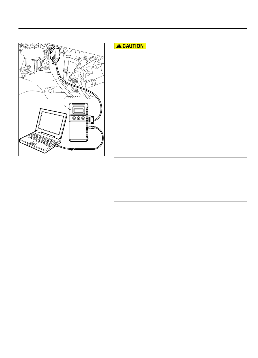
STEP 1. Using scan tool MB991958, read CAN bus the
diagnostic trouble code.

ZC501967

AC404789

ZC5019680000

MB991824

MB991827

MB991910

Data link

connector

To prevent damage to scan tool MB991958, always turn the
ignition  switch  to  the  "LOCK"  (OFF)  position  before
connecting or disconnecting scan tool MB991958.

(1)

Connect scan tool MB991958. Refer to "How to connect scan
tool (M.U.T.-III) P.42B-10."

(2)

Turn the ignition switch to the "ON" position.

(3)

Check whether the CAN bus lines related DTC is set.

(4)

Turn the ignition switch to the "LOCK" (OFF) position.

Q:Is the DTC set?

YES:

 Repair the CAN bus line (Refer to GROUP 54D, CAN bus

diagnostics table P.54D-17).

NO:

 Go to Step 2.

STEP 2. Check KOS-ECU connector C-102 for loose,
corroded or damaged terminals, or terminals pushed back
in the connector.

Q:Is KOS-ECU connector C-102 in good condition?

YES:

 Go to Step 3.

NO:

 Repair or replace the damaged component(s). Refer to

GROUP 00E, Harness Connector Inspection P.00E-2.

STEP 3. Check the wiring harness between KOS-ECU and
each interior and exterior antenna.
Check the following wiring harnesses for open circuit and short
to ground.

Wiring harness between KOS-ECU connector C-102 (terminal
No.  40)  and  exterior  transmitter  antenna  assembly  (driver's
side) connector D-131 (terminal No. 1)

Wiring harness between KOS-ECU connector C-102 (terminal
No.  40)  and  exterior  transmitter  antenna  assembly  (front
passenger's side) connector D-101 (terminal No. 1)

Wiring harness between KOS-ECU connector C-102 (terminal
No.  40)  and  interior  transmitter  antenna  (front)  connector
D-124 (terminal No. 1)

Wiring harness between KOS-ECU connector C-102 (terminal
No. 40) and interior transmitter antenna (rear: driver's side)
connector D-112 (terminal No. 1)

Wiring harness between KOS-ECU connector C-102 (terminal
No.  40)  and  interior  transmitter  antenna  (rear:  front
passenger's side) connector D-106 (terminal No. 1)

KEYLESS OPERATION SYSTEM (KOS)

42B-67

DIAGNOSIS

Wiring harness between KOS-ECU connector C-102 (terminal
No. 40) and exterior transmitter antenna assembly (liftgate)
connector F-14 (terminal No. 3)

NOTE: 

Also check intermediate connectors C-22 and F-17 for

loose, corroded, or damaged terminals, or terminals pushed
back in the connector. If intermediate connectors C-22 and
F-17 is damaged, repair or replace the damaged component(s)
as described in GROUP 00E, Harness Connector Inspection P.
00E-2.

Q:Are  the  wiring  harness  between  KOS-ECU  connector

C-102  and  each  interior  and  exterior  antenna  in  good

condition?

YES:

 Go to Step 4.

NO:

 The wiring harness may be damaged or the connector

(s) may have loose, corroded or damaged terminals, or
terminals pushed back in the connector. Repair the wiring
harness as necessary.

STEP 4. Check whether the diagnostic trouble code is reset.

(1)

Erase the diagnostic trouble code.

(2)

Turn the ignition switch from the LOCK (OFF) position to the
ON position.

(3)

Check if the diagnostic trouble code is set.

Q:Is the diagnostic trouble code set?

YES:

 Replace KOS-ECU and register the ID codes. (Refer

to P.42B-163.)

NO:

 The procedure is complete.

DTC B2413: STL unit power voltage

M14209100127USA0000010000

If the DTC B2413 is set in the steering lock unit,
diagnose the CAN bus lines. If there is any fault
in  the  CAN  bus  lines,  an  incorrect  diagnostic
trouble  code  may  be  set.  In  this  case,  the  set
DTC is not highly reliable.

Whenever the steering lock unit (integrated in
the  key  reminder  switch)  is  replaced,  ensure
that the communication circuit is normal.

42B-68

KEYLESS OPERATION SYSTEM (KOS)

DIAGNOSIS

 Key Reminder Switch and KOS-ECU Circuit

KOS-ECU

KEY
REMINDER
SWITCH

ZC600875

Connector: C-102

0028

ZC6008770002

Connector: C-211

DTC SET CONDITION
If KOS-ECU detects an abnormality in power supply
of  the  steering  lock  unit,  KOS-ECU  sets  the  DTC
B2413.

TECHNICAL DESCRIPTION (COMMENT)
If  an  abnormality  in  power  supply  of  the  exterior  or
interior transmitter antenna is detected when power

supply of it is turned on, KOS-ECU determines that
there is a problem.

TROUBLESHOOTING HINTS

Damaged wiring harness and connectors

Malfunction of the steering lock unit (integrated into
the key reminder switch)

Malfunction of the KOS-ECU

KEYLESS OPERATION SYSTEM (KOS)

42B-69

DIAGNOSIS

DIAGNOSIS

Required Special Tools:

MB991958: Scan Tool (M.U.T.-III Sub Assembly)

MB991824: Vehicles Communication Interface (V.C.I.)

MB991827: M.U.T.-III USB Cable

MB991910:  M.U.T.-III  Main  Harness  A  (Vehicles  with
CAN communication system)

STEP 1. Using scan tool MB991958, diagnose the CAN bus
line.

ZC501967

AC404789

ZC5019680000

MB991824

MB991827

MB991910

Data link

connector

To prevent damage to scan tool (MB991958), always turn
the  ignition  switch  to  the  "LOCK"  (OFF)  position  before
connecting or disconnecting scan tool (MB991958).

(1)

Connect scan tool MB991958 to the data link connector.

(2)

Turn the ignition switch to the "ON" position.

(3)

Diagnose the CAN bus line.

(4)

Turn the ignition switch to the "LOCK" (OFF) position.

Q:Is the CAN bus line found to be normal?

YES:

 Go to Step 2.

NO:

 Repair the CAN bus line. (Refer to GROUP 54D,

Diagnosis P.54D-17).

STEP 2. Check key reminder switch connector C-211 for
loose, corroded or damaged terminals, or terminals pushed
back in the connector.

Q:Is  tye  key  reminder  switch  connector  C-211  in  good

condition?

YES:

 Go to Step 3.

NO:

 Repair the defective connector.

STEP 3. Check the power supply circuit to the key reminder
switch. Measure the voltage at key reminder switch
connector C-211.

(1)

Disconnect the connector, and measure at the harness side.

(2)

Turn the ignition push switch to the ON position.

42B-70

KEYLESS OPERATION SYSTEM (KOS)

DIAGNOSIS


Content   ..  779  780  781  782   ..