Mitsubishi Outlander XL. Manual - part 711


  Index      Mitsubishi     Mitsubishi Outlander XL - service repair manual 2007 year


Search            


Content   ..  709  710  711  712   ..


Mitsubishi Outlander XL. Manual - part 711


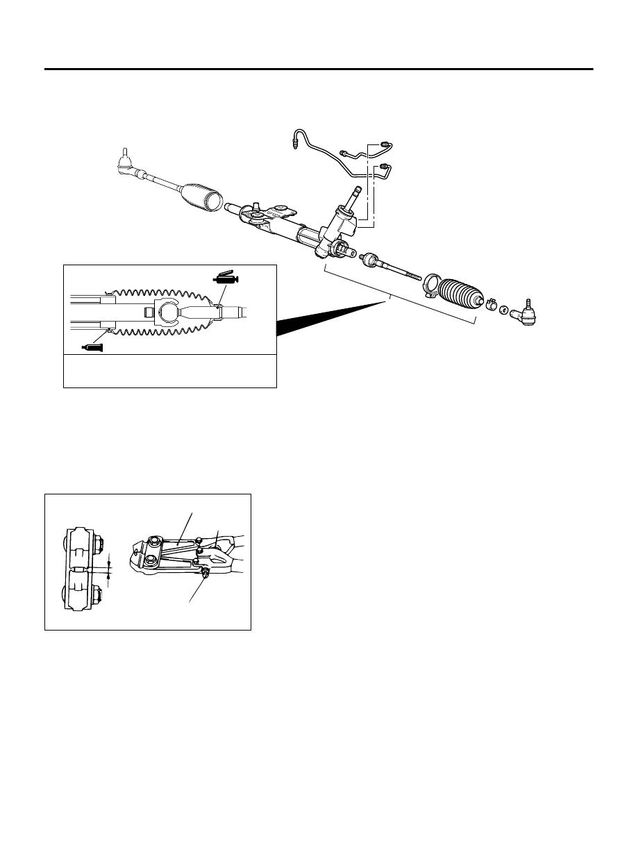
GREASE/SEALANT APPLICATION POINTS

ZC5019760000

Grease: Silicone grease

Sealant: 3M™ AAD Part No. 8663 or equivalent


ASSEMBLY SERVICE POINT

>>A<< BAND INSTALLATION

ZC5019770000

W

MB991561

Adjusting bolt

Stopper

1.

Turn the adjusting bolt for the boot band clipping tool (Special
tool: MB991561) to adjust the opening dimension (W) to the
standard value.

Standard value (W): 2.9 mm (0.11 inch)
When opening dimension is more than 2.9 mm (0.11
inch)
Tighten the adjusting bolt.
When opening dimension is less than 2.9 mm (0.11
inch)
Loosen the adjusting bolt.

NOTE:

The  adjusting  bolt  changes  W  approximately  0.7  mm  for
each rotation.

Do not rotate the adjusting bolt more than one rotation.

POWER STEERING

37-33

POWER STEERING GEAR BOX AND LINKAGE

ZC502005

MB991561

0000

Secure the gear housing, and crimp the crimping part of
the band firmly with the tip of the special tool.

Crimp  the  boot  band  securely  until  the  special  tool
contacts the stopper.

2.

Use the special tool to crimp the boot band.

ZC5020060000

A

3.

Check that the crimping width of the boot band (A) is within
the range of the standard value.

Standard value (A): 2.4 - 2.8 mm (0.09 - 0.11 inch)
When the crimping width is greater than 2.8 mm (0.11
inch)
Readjust  the  value  W  described  in  Step  1  to  the
following formula, and perform the operation in Step
2 again.
W=5.5-A (Example: When A is 2.9, W is 2.6.)
When the crimping width is less than 2.4 mm (0.09
inch)
Remove  the  boot  band,  readjust  the  value  W
described  in  Step  1  to  the  following  formula,  and
perform the Steps 2 and 3 using a new boot band.
W=5.5-A (Example: When A is 2.3, W is 3.2.)


>>B<< TIE-ROD END/LOCKING NUT INSTALLATION

ZC502007

207 mm

Edge of bellows 
assembly groove

Lock nut

0000

Screw in the tie-rod to the length shown in the figure, and hand-
tighten the locking nut.

NOTE: 

Install the steering gear & linkage to the body,

adjust the toe-in, and then tighten the locking nut to the
specified torque.

POWER STEERING OIL PUMP ASSEMBLY

REMOVAL AND INSTALLATION

M13702000052USA0000010000

Pre-removal operation

Power  Steering  Fluid  Draining  (Refer  to  P.
37-17.)

Post-installation operation

Engine Room Side Cover (R) Installation (Refer
to  GROUP  51A  -  Under  Cover  Removal  and
Installation P.51A-18.)

37-34

POWER STEERING

POWER STEERING OIL PUMP ASSEMBLY

Engine Room Side Cover (R) Removal (Refer to
GROUP  51A  -  Under  Cover  Removal  and
Installation P.51A-18.)

Power  Steering  Fluid  Refilling  and  Bleeding
(Refer to P.37-18.)

Drive Belt Tension Adjustment (Refer to GROUP
11A - Engine Adjustment P.11A-9.)

ZC5018460000

1

2

5

6

7

8

3

4

N

13 ± 2 N·m 
110 ± 22 in-lb

25 ± 4 N·m 
19 ± 3 ft-lb

57 ± 7 N·m 
42 ± 5 ft-lb

50 ± 7 N·m 
37 ± 5 ft-lb

Removal steps

1.

Generator  and  Others  Belt  (Refer  to
GROUP  11A  -  Crankshaft  Pulley
Removal and Installation P.11A-21.)

2.

Suction hose connection

3.

Eye bolt

4.

Gasket

5.

Pressure hose connection

<<A>>

6.

Oil pump assembly

7.

Heat protector

8.

Power steering pump bracket

POWER STEERING

37-35

POWER STEERING OIL PUMP ASSEMBLY

REMOVAL SERVICE POINTS

<<A>> OIL PUMP ASSEMBLY REMOVAL

ZC601962

Oil pump assembly

Stabilizer link 

Stabilizer bar 

0000

When removing the oil pump assembly, remove the stabilizer
link and stabilizer bar bracket, shift the stabilizer bar to the left
of  the  vehicle,  and  then  remove  the  assembly  from  the  front
wheel house (right side).(Refer to GROUP 33 - Stabilizer Bar
Removal And Installation P.33-16.)

INSPECTION

M13702000053USA0000010000

Check the drive belt for cracks.

Check the pulley for uneven rotation.

DISASSEMBLY AND ASSEMBLY

M13702000054USA0000010000

Do  not  use  ATF-SP  II  M  and  ATF-SP  III  for  the
power steering fluid.

37-36

POWER STEERING

POWER STEERING OIL PUMP ASSEMBLY


Content   ..  709  710  711  712   ..