Mitsubishi Outlander XL. Manual - part 695
SPECIAL TOOL
M13506100002USA0000010000
Tool
Tool number and
name
Supersession
Application
MB991910
MB991826
YB9919580000
MB991911
MB991914
MB991824
MB991827
MB991825
Do not use
Do not use
a
b
c
d
e
f
g
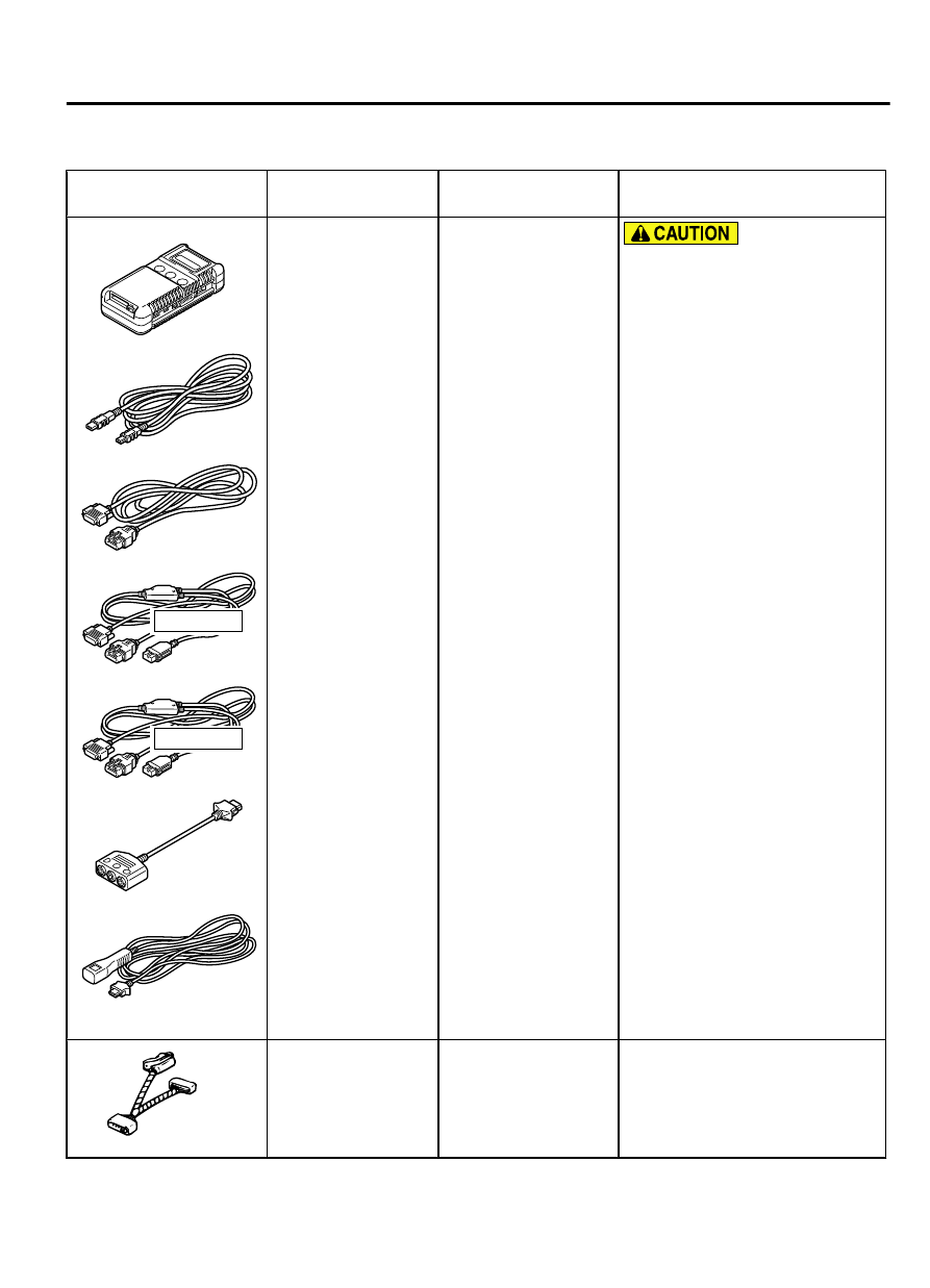
MB991958
a.
MB991824
b.
MB991827
c.
MB991910
d.
MB991911
e.
MB991914
f.
MB991825
g.
MB991826
M.U.T.-III
sub
assembly
a.
Vehicle
communication
interface (V.C.I.)
b.
M.U.T.-III
USB
cable
c.
M.U.T.-III
main
harness
A
(Vehicles
with
CAN
communication
system)
d.
M.U.T.-III
main
harness
B
(Vehicles without
CAN
communication
system)
e.
M.U.T.-III
main
harness C (for
Daimler Chrysler
models only)
f.
M.U.T.-III
measurement
adapter
g.
M.U.T.-III trigger
harness
MB991824-KIT
NOTE:
G: MB991826
M.U.T.-III Trigger
Harness is not
necessary when
pushing V.C.I. ENTER
key.
M.U.T.-III main harness A
(MB991910) should be used.
M.U.T.-III main harness B and C
should not be used for this
vehicle.
ASC check (Diagnostic trouble
code display, service data display
and calibration by scan tool )
MB991997
MB991997
ASC check harness
Voltage inspection at ASC-ECU
terminals
ACTIVE SKID CONTROL SYSTEM (ASC)
35C-187
SPECIAL TOOL