Mitsubishi Outlander XL. Manual - part 657


  Index      Mitsubishi     Mitsubishi Outlander XL - service repair manual 2007 year


Search            


Content   ..  655  656  657  658   ..


Mitsubishi Outlander XL. Manual - part 657


YES:

 Go to Step 3.

NO:

 Repair the CAN bus lines. (Refer to GROUP 54D - CAN

Bus Diagnostics table P.54D-17.) On completion, go to
Step 2.

STEP 2. Diagnostic trouble code recheck after resetting
CAN bus lines

Q:Is DTC C1011 set?

YES:

 Go to Step 3.

NO:

 The procedure is complete.

STEP 3. M.U.T.-III diagnostic trouble code
Check that the diagnostic trouble code No. C100A is also set.

Q:Is DTC C100A also set?

YES:

 Perform the diagnosis for the diagnostic trouble

code No. C100A. (Refer to P.35C-14.)

NO:

 Go to Step 4.

STEP 4. Check for wheel speed sensor installation
Check  how  the  wheel  speed  sensor  <FL>  is  installed
(Disconnection  of  wheel  speed  sensor,  loose  mounting  bolt,
etc.).

Q:Is the check result normal?

YES:

 Go to Step 5.

NO:

 Reinstall the wheel speed sensor correctly.

STEP 5. Check for wheel speed sensor as a single unit

Q:Is the check result normal?

YES:

 Go to Step 6.

NO:

 Replace the wheel speed sensor.

STEP 6. Check for wheel bearing looseness

NOTE: 

Loose wheel bearing may increase the gap between the

wheel speed sensor and the wheel speed detection magnet
encoder. Check the wheel bearing <FL> for looseness. (Refer
to GROUP 26 - On-vehicle Service P.26-8.)

Q:Is the check result normal?

YES:

 Go to Step 7.

NO:

 Replace the wheel bearing.

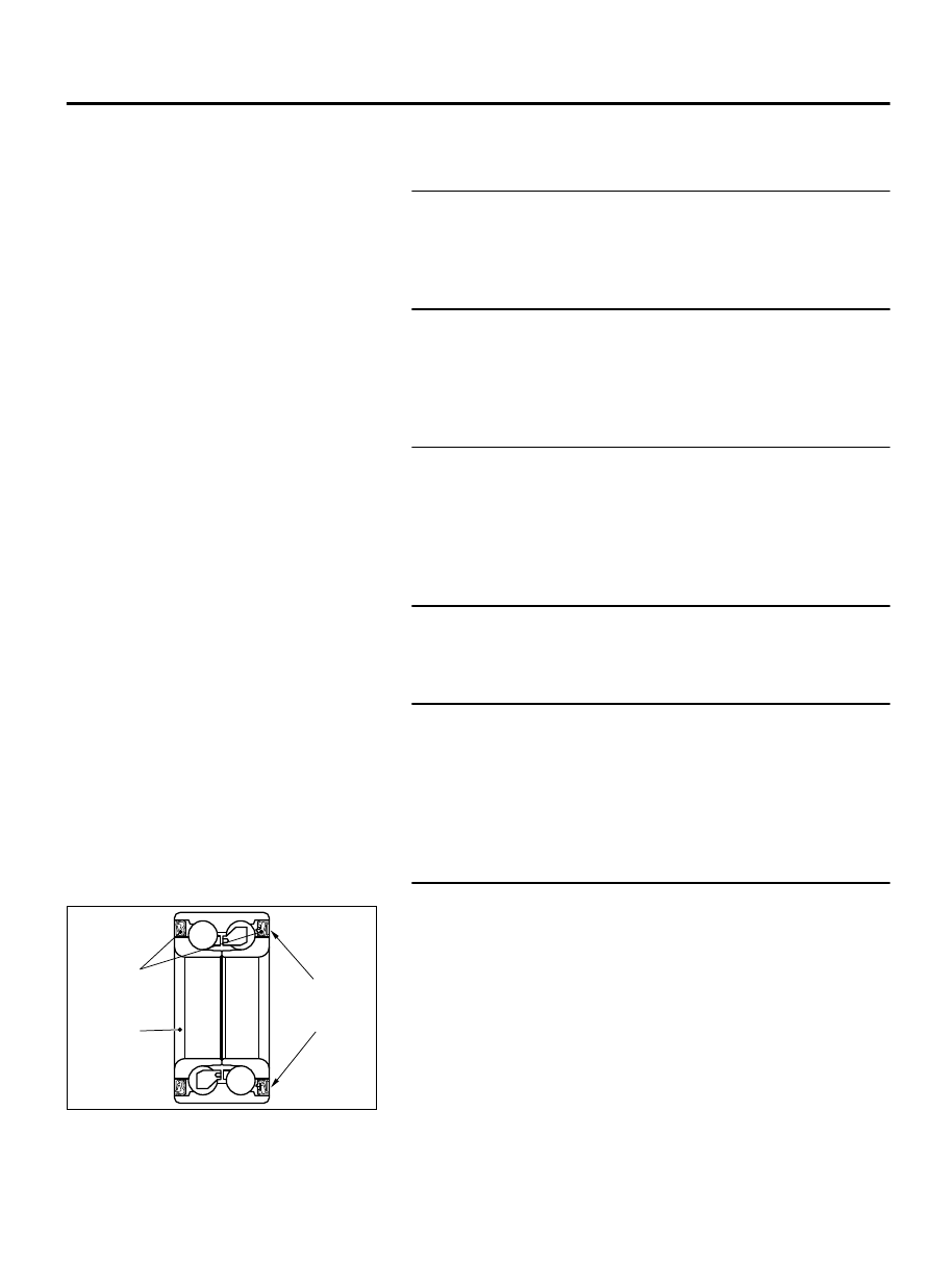
STEP 7. Check of wheel speed detection encoder

ZC601555

Oil seal

Magnetic
encoder

0000

Wheel
bearing

Check  the  encoder  for  adhesion  of  foreign  materials  or
deformation.

Q:Is the check result normal?

YES:

 Go to Step 8.

NO:

 Remove the foreign materials and clean the encoder

so as not to disturb the magnetization pattern on it while
taking care of the magnet, magnetic substance, and
magnetic attraction. When the encoder is deformed,
replace the wheel bearing.

ACTIVE SKID CONTROL SYSTEM (ASC)

35C-35

DIAGNOSIS

STEP 8. Voltage measurement at the A-02 ASC-ECU
connector

ZC601293 0001

ASC-ECU

MB991997

Check harness

A-02 ASC-ECU 
Harness connector

(1)

Disconnect  the  ASC-ECU  connector,  connect  special  tool
MB991997 to the harness-side connector, and then measure
the resistance at special tool connector side.

NOTE: 

Do not connect the special tool MB991997 to ASC-

ECU.

(2)

Turn the ignition switch to the ON position.

(3)

Measure the voltage between the wheel speed sensor power
supply terminal (signal terminal) No. 45/the ground terminal
No. 46 and the body ground.

OK: 0 volt

Q:Is the check result normal?

YES:

 Go to Step 9.

NO (Not normal at the terminal No. 45 or 46):

 Go to Step

10.

STEP 9. Resistance measurement at A-02 ASC-ECU
connector

ZC601293 0002

ASC-ECU

MB991997

Check harness

A-02 ASC-ECU 
harness connector

(1)

Disconnect  the  ASC-ECU  connector,  connect  special  tool
MB991997 to the harness-side connector, and then measure
the resistance at special tool connector side.

NOTE: 

Do not connect the special tool MB991997 to ASC-

ECU.

(2)

Resistance between the wheel speed sensor power supply
terminal (signal terminal) No. 45/the ground terminal No. 46
and the body ground

OK: No continuity

Q:Is the check result normal?

YES:

 Go to Step 11.

NO (Not normal at the terminal No. 45 or 46):

 Go to Step

10.

STEP 10. Connector check: A-02 ASC-ECU connector, A-11
wheel speed sensor <FL> connector

Q:Is the check result normal?

35C-36

ACTIVE SKID CONTROL SYSTEM (ASC)

DIAGNOSIS

YES:

 The short circuit in the wheel speed sensor <FL>

circuit may be present. Repair the wiring harness between
the A-02 ASC-ECU connector terminal No. 45/46 and the A-11
wheel speed sensor <FL> connector terminal No. 1/2.

NO:

 Repair the defective connector.

STEP 11. Voltage measurement at the A-02 ASC-ECU
connector

ZC601292 0001

ASC-ECU

MB991997

Check harness

A-02 ASC-ECU 
harness connector

(1)

Disconnect  the  ASC-ECU  connector,  connect  special  tool
MB991997  to  the  ASC-ECU-side  connector  and  harness-
side connector, and then measure the voltage at the special
tool connector side.

(2)

Turn the ignition switch to the ON position.

(3)

Measure the voltage between the wheel speed sensor circuit
power supply terminal (signal terminal) No. 45 and the body
ground.

OK: Approximately battery voltage

Q:Is the check result normal?

YES:

 Go to Step 14.

NO:

 Go to Step 12.

STEP 12. Connector check: A-02 ASC-ECU connector, A-11
wheel speed sensor <FL> connector

Q:Is the check result normal?

YES:

 Go to Step 13.

NO:

 Repair the defective connector.

STEP 13. Wiring harness check between A-02 ASC-ECU
connector terminal No. 45/46 and A-11 wheel speed sensor
<FL> connector terminal No. 1/2

Check for open circuit in wheel speed sensor <FL> circuit.

Q:Is the check result normal?

YES:

 Replace the wheel speed sensor.

NO:

 Repair the wiring harness.

STEP 14. Check whether the diagnostic trouble code is
reset.

(1)

Erase the diagnostic trouble code.

(2)

Drive the vehicle at 12mph (20 km/h) or more.

NOTE: 

The ABS warning light does not turn OFF in some

cases unless the vehicle runs at 12mph (20 km/h) or
higher.

Q:Is DTC C1011 set?

ACTIVE SKID CONTROL SYSTEM (ASC)

35C-37

DIAGNOSIS

YES:

 Replace the ASC-ECU.

NO:

 Intermittent malfunction. (Refer to GROUP 00 - How

to Cope with Intermittent Malfunction P.00-15.)

DTC C101C Abnormality in FR wheel speed sensor signal

M13506100015USA0000010000

Wheel Speed Sensor Circuit

ASC-ECU

FRONT 
WHEEL 
SPEED 
SENSOR
(LH)

FRONT 
WHEEL 
SPEED 
SENSOR
(RH)

REAR 
WHEEL 
SPEED 
SENSOR
(LH)

REAR 
WHEEL 
SPEED 
SENSOR
(RH)

If there is any problem in the CAN bus lines, an incorrect
diagnostic trouble code may be set. Prior to this diagnosis,
diagnose the CAN bus lines. (Refer to GROUP 54D, Trouble
code diagnosis P.54D-17
).

CIRCUIT OPERATION

The  wheel  speed  sensor  is  a  kind  of  a  pulse  generator.  It
consists of encoders (a plate on which north and south pole
sides of the magnets are arranged alternately) for detecting
the  wheel  speed  which  rotates  at  the  same  speed  of  the
wheels  and  wheel  speed  sensors.  This  sensor  outputs
frequency pulse signals in proportion to the wheel speed.

The pulse signals, which the wheel speed sensor creates, are
sent to ASC-ECU. ASC-ECU uses the frequency of the pulse
signals to determine the wheel speed.

35C-38

ACTIVE SKID CONTROL SYSTEM (ASC)

DIAGNOSIS


Content   ..  655  656  657  658   ..