Mitsubishi Outlander XL. Manual - part 656


  Index      Mitsubishi     Mitsubishi Outlander XL - service repair manual 2007 year


Search            


Content   ..  654  655  656  657   ..


Mitsubishi Outlander XL. Manual - part 656


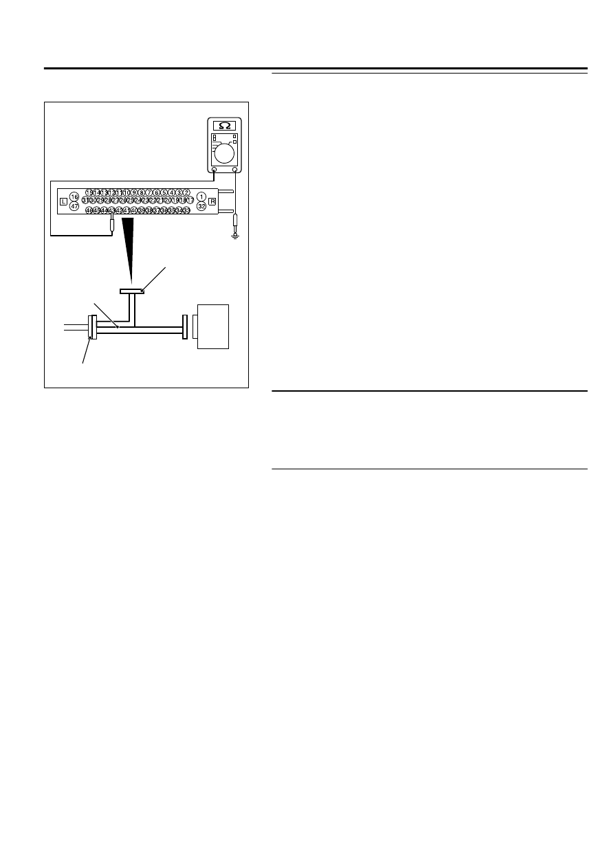
STEP 7. Resistance measurement at A-02 ASC-ECU
connector

ZC601293 0007

ASC-ECU

MB991997

Check harness

A-02 ASC-ECU 
harness connector

(1)

Disconnect  the  ASC-ECU  connector,  connect  special  tool
MB991997 to the harness-side connector, and then measure
the resistance at the special tool connector side.

NOTE: 

Do not connect the special tool MB991997 to ASC-

ECU.

(2)

Resistance between the wheel speed sensor power supply
terminal (signal terminal) No. 43/the ground terminal No. 42
and the body ground

OK: No continuity

Q:Is the check result normal?

YES:

 Go to Step 10.

NO (Not normal at the terminal No. 43 or 42):

 Go to Step

8.

STEP 8. Connector check: A-02 ASC-ECU connector, D-133
wheel speed sensor <RR> connector

Q:Is the check result normal?

YES:

 Go to Step 9.

NO:

 Repair the defective connector.

STEP 9. Wiring harness check between A-02 ASC-ECU
connector terminal No. 43/42 and D-133 wheel speed sensor
<RR> connector terminal No. 1/2

Check for short circuit in wheel speed sensor <RR> circuit

Q:Is the check result normal?

YES:

 Replace the wheel speed sensor <RR>.

NO:

 Repair the wiring harness.

ACTIVE SKID CONTROL SYSTEM (ASC)

35C-31

DIAGNOSIS

STEP 10. Voltage measurement at the A-02 ASC-ECU
connector

ZC601292 0004

ASC-ECU

MB991997

Check harness

A-02 ASC-ECU 
harness connector

(1)

Disconnect  the  ASC-ECU  connector,  connect  special  tool
MB991997  to  the  ASC-ECU-side  connector  and  harness-
side connector, and then measure the voltage at the special
tool connector side.

(2)

Turn the ignition switch to the ON position.

(3)

Measure the voltage between the wheel speed sensor circuit
power supply terminal (signal terminal) No. 43 and the body
ground.

OK: Approximately battery voltage

Q:Is the check result normal?

YES:

 Go to Step 13.

NO:

 Go to Step 11.

STEP 11. Connector check: A-02 ASC-ECU connector,
D-133 wheel speed sensor <RR> connector

Q:Is the check result normal?

YES:

 Go to Step 12.

NO:

 Repair the defective connector.

STEP 12. Wiring harness check between A-02 ASC-ECU
connector terminal No. 43/42 and D-133 wheel speed sensor
<RR> connector terminal No. 1/2

Check for open circuit in wheel speed sensor <RR> circuit

Q:Is the check result normal?

YES:

 Replace the wheel speed sensor.

NO:

 Repair the wiring harness.

STEP 13. Check for wheel speed sensor as a single unit
Refer to P.35C-197.

Q:Is the check result normal?

YES:

 Go to Step 14.

NO:

 Replace the wheel speed sensor.

STEP 14. Check whether the diagnostic trouble code is
reset.

(1)

Erase the diagnostic trouble code.

(2)

Drive the vehicle at 12mph (20 km/h) or more.

NOTE: 

The ABS warning light does not turn OFF in some

cases unless the vehicle runs at 12mph (20 km/h) or
higher.

35C-32

ACTIVE SKID CONTROL SYSTEM (ASC)

DIAGNOSIS

Q:Is DTC C102B set?

YES:

 Replace the ASC-ECU.

NO:

 Intermittent malfunction (Refer to GROUP 00 - How to

Cope with Intermittent Malfunction P.00-15).

DTC C1011: Abnormality in FL wheel speed sensor signal

M13506100014USA0000010000

Wheel Speed Sensor Circuit

ASC-ECU

FRONT 
WHEEL 
SPEED 
SENSOR
(LH)

FRONT 
WHEEL 
SPEED 
SENSOR
(RH)

REAR 
WHEEL 
SPEED 
SENSOR
(LH)

REAR 
WHEEL 
SPEED 
SENSOR
(RH)

If there is any problem in the CAN bus lines, an incorrect
diagnostic trouble code may be set. Prior to this diagnosis,
diagnose the CAN bus lines. (Refer to GROUP 54D, Trouble
code diagnosis P.54D-17).

CIRCUIT OPERATION

The  wheel  speed  sensor  is  a  kind  of  a  pulse  generator.  It
consists of encoders (a plate on which north and south pole
sides of the magnets are arranged alternately) for detecting
the  wheel  speed  which  rotates  at  the  same  speed  of  the
wheels  and  wheel  speed  sensors.  This  sensor  outputs
frequency pulse signals in proportion to the wheel speed.

The pulse signals, which the wheel speed sensor creates, are
sent to ASC-ECU. ASC-ECU uses the frequency of the pulse
signals to determine the wheel speed.

ACTIVE SKID CONTROL SYSTEM (ASC)

35C-33

DIAGNOSIS

DTC SET CONDITIONS
ASC-ECU monitors the signals from each wheel speed sensor
while the vehicle is being driven. If any fault below is found in
these sensor signals, ASC-ECU will set the relevant diagnostic
trouble code.

Irregular change in the wheel speed sensor signal

Wheel speed sensor signal continuously indicates high value.

PROBABLE CAUSES

Current trouble

Excessive  gap  between  the  wheel  speed  sensor  and  the
wheel speed detection encoder

Adhesion of foreign materials on the wheel speed sensor

Adhesion of foreign materials on the wheel speed detection
encoder

Wheel bearing malfunction

Malfunction of wheel speed sensor

Damaged wiring harness and connectors

External noise interference

Improper installation of the wheel speed sensor

Deformation of the wheel speed detection encoder

ASC-ECU malfunction

Disturbance  of  magnetization  pattern  for  wheel  speed
detection encoder

Past trouble

When the diagnostic trouble code No. C100A is also set, carry
out diagnosis with particular emphasis on wiring harness and
connector failures between ASC-ECU and the wheel speed
sensor. For diagnosis procedures, refer to How to treat past
trouble (Refer to GROUP 00 - How to Cope with Intermittent
Malfunction P.00-15).

When the diagnostic trouble code No. C100A is not set, the
following conditions may be present:

Right or/and left wheels are rotated.

Unstable vehicle attitude

External noise interference

Vehicle ran with the parking brake applied.

DIAGNOSIS

Required Special Tools:

MB991958: Scan Tool (M.U.T.-III Sub Assembly)

MB991824: Vehicle Communication Interface (V.C.I.)

MB991827: M.U.T.-III USB Cable

MB991910: M.U.T.-III Main Harness A

MB991997: ASC check harness

STEP 1. M.U.T.-III CAN bus diagnostics
Use scan tool to diagnose the CAN bus lines.

Q:Is the check result normal?

35C-34

ACTIVE SKID CONTROL SYSTEM (ASC)

DIAGNOSIS


Content   ..  654  655  656  657   ..