Mitsubishi Outlander XL. Manual - part 638


  Index      Mitsubishi     Mitsubishi Outlander XL - service repair manual 2007 year


Search            


Content   ..  636  637  638  639   ..


Mitsubishi Outlander XL. Manual - part 638


Q:Is the charging system in good condition?

YES:

 Replace the battery. Then go to Step 9.

NO:

 Repair or replace the charging system component(s).

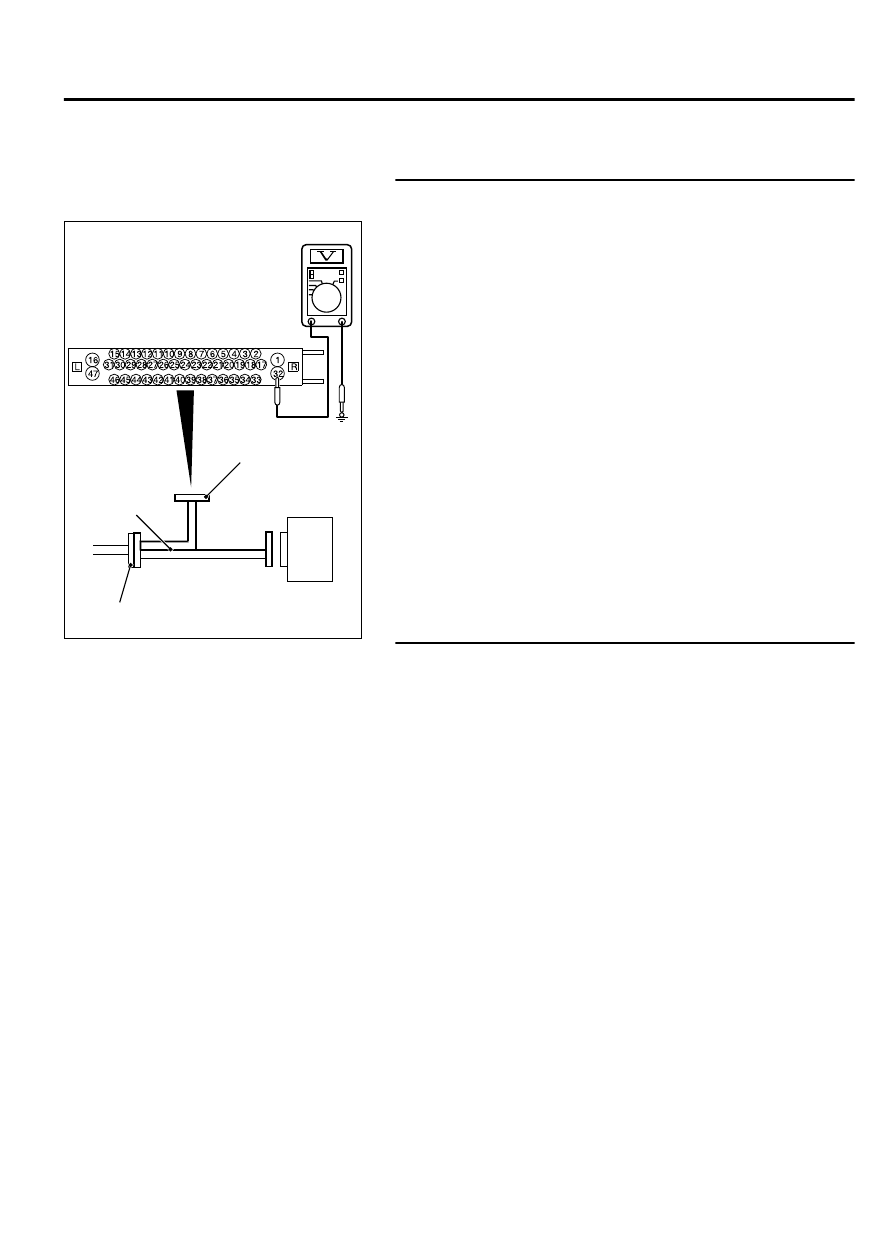
STEP 5. Voltage measurement at the A-01 ABS-ECU
connector

ZC601293 0008

ASC-ECU

MB991997

Check harness

A-02 ASC-ECU 
harness connector

(1)

Disconnect the connector, connect special tool MB991974 to
the harness-side connector, and measure the voltage at the
special tool connector side.

NOTE: 

Do not connect the special tool MB991974 to ABS-

ECU.

(2)

Turn the ignition switch to the ON position.

(3)

Measure the voltage between the terminal No. 26 and the
body ground.

OK: 12 volts (Battery voltage)

Q:Is the check result normal?

YES:

 Go to Step 6.

NO:

 Go to Step 7.

STEP 6. Connector check: A-01 ABS-ECU connector

Q:Is the check result normal?

YES:

 The open or short circuit may be present in the

power supply circuit. Repair the wiring harness between
the A-01 ABS-ECU connector terminal No. 26 and the fusible
link No. 27.

NO:

 Repair the defective connector.

ANTI-LOCK BRAKING SYSTEM (ABS)

35B-115

ANTI-LOCK BRAKING SYSTEM (ABS) DIAGNOSIS

STEP 7. Resistance measurement at A-01 ABS-ECU
connector

ZC601293 0025

Check harness

ABS-ECU

MB991974

A-01 ABS-ECU 
harness connector

(1)

Disconnect the connector, connect special tool MB991974 to
the harness-side connector, and measure the voltage at the
special tool connector side.

NOTE: 

Do not connect the special tool MB991974 to ABS-

ECU.

(2)

Resistance between the terminal No. 1 and the body ground

OK: Continuity exists (2 ohms or less)

Q:Is the check result normal?

YES:

 Go to Step 9.

NO:

 Go to Step 8.

STEP 8. Connector check: A-01 ABS-ECU connector

Q:Is the check result normal?

YES:

 An open circuit may be present in the ground

circuit. Repair the wiring harness between the A-01 ABS-
ECU connector terminal No.14 and the body ground.

NO:

 Repair the defective connector.

STEP 9. Check whether the diagnostic Trouble code is
reset.

(1)

Erase the diagnostic trouble code.

(2)

Turn the ignition switch to the "LOCK" (OFF) position.

(3)

Turn the ignition switch to the "ON" position.

Q:Is any DTC set?

YES (DTC C1608 is set):

 Replace the ABS-ECU.

YES (DTC other than C1608 is set):

 Carry out the

applicable troubleshooting for the diagnostic trouble
code.

NO:

 This diagnosis is complete.

35B-116

ANTI-LOCK BRAKING SYSTEM (ABS)

ANTI-LOCK BRAKING SYSTEM (ABS) DIAGNOSIS

DTC U0001: Bus-off

M13502000946USA0000010000

If  diagnostic  trouble  code  U0001  is  set  in  ABS-ECU,
always diagnose the CAN bus line. If there is any fault in
the CAN bus lines, an incorrect diagnostic trouble code
may be set. In this case, the set diagnostic trouble code
is not highly reliable.

Before replacing the ECU, ensure that the communication
circuit is normal.

DTC SET CONDITIONS
This diagnostic trouble code is set when ABS-ECU has ceased
the CAN communication (bus off).

PROBABLE CAUSES

Wiring harness or connector failure of CAN bus line

ABS-ECU malfunction

DIAGNOSIS

Required Special Tools:

MB991958: Scan Tool (M.U.T.-III Sub Assembly)

MB991824: Vehicle Communication Interface (V.C.I.)

MB991827: M.U.T.-III USB Cable

MB991910: M.U.T.-III Main Harness A

STEP 1. M.U.T.-III CAN bus diagnostics
Use scan tool to diagnose the CAN bus lines.

Q:Is the check result normal?

YES:

 Go to Step 2.

NO:

 Repair the CAN bus lines. (Refer to GROUP 54D - CAN

Bus Diagnostics table P.54D-17.) On completion, go to
Step 3.

STEP 2. Check whether the diagnostic trouble code is reset.

Q:Is DTC U0001 set?

YES:

 Replace the ABS-ECU.

NO:

 If the trouble symptom is resolved, an intermittent

malfunction such as poorly engaged connector(s) or wiring
harness is suspected. (Refer to GROUP 00 - How to Cope
with Intermittent Malfunction P.00-15.)

STEP 3. Check whether the diagnostic trouble code is reset.

Q:Is DTC U0001 set?

YES:

 Return to Step 1.

NO:

 The procedure is complete.

ANTI-LOCK BRAKING SYSTEM (ABS)

35B-117

ANTI-LOCK BRAKING SYSTEM (ABS) DIAGNOSIS

DTC U0100: Engine time-out error
DTC U0114: AWD time-out error
DTC U0141: ETACS time-out error

M13502000947USA0000010000

If the diagnostic trouble codes U0100, U0114 and U0141
are set in ABS-ECU, always diagnose the CAN bus line. If
there  is  any  fault  in  the  CAN  bus  lines,  an  incorrect
diagnostic trouble code may be set. In this case, the set
diagnostic trouble code is not highly reliable.

Before replacing the ECU, ensure that the communication
circuit is normal.

CIRCUIT OPERATION
ABS-ECU communicates with the engine ECU, AWD-ECU and
ETACS-ECU via the CAN bus lines.

DTC SET CONDITIONS
This diagnostic trouble code is set if ABS-ECU cannot receive
the signal sent from other ECU for a certain period.

PROBABLE CAUSES

DTC U0100

Wiring harness or connector failure of CAN bus line

Engine ECU malfunction

ABS-ECU malfunction

DTC U0114

Wiring harness or connector failure of CAN bus line

AWD-ECU malfunction

ABS-ECU malfunction

DTC U0141

Wiring harness or connector failure of CAN bus line

Malfunction of ETACS-ECU

ABS-ECU malfunction

DIAGNOSIS

Required Special Tools:

MB991958: Scan Tool (M.U.T.-III Sub Assembly)

MB991824: Vehicle Communication Interface (V.C.I.)

MB991827: M.U.T.-III USB Cable

MB991910: M.U.T.-III Main Harness A

STEP 1. M.U.T.-III CAN bus diagnostics
Use scan tool to diagnose the CAN bus lines.

35B-118

ANTI-LOCK BRAKING SYSTEM (ABS)

ANTI-LOCK BRAKING SYSTEM (ABS) DIAGNOSIS


Content   ..  636  637  638  639   ..