Mitsubishi Outlander XL. Manual - part 633


  Index      Mitsubishi     Mitsubishi Outlander XL - service repair manual 2007 year


Search            


Content   ..  631  632  633  634   ..


Mitsubishi Outlander XL. Manual - part 633


DTC C1000: Abnormality in stop light switch circuit

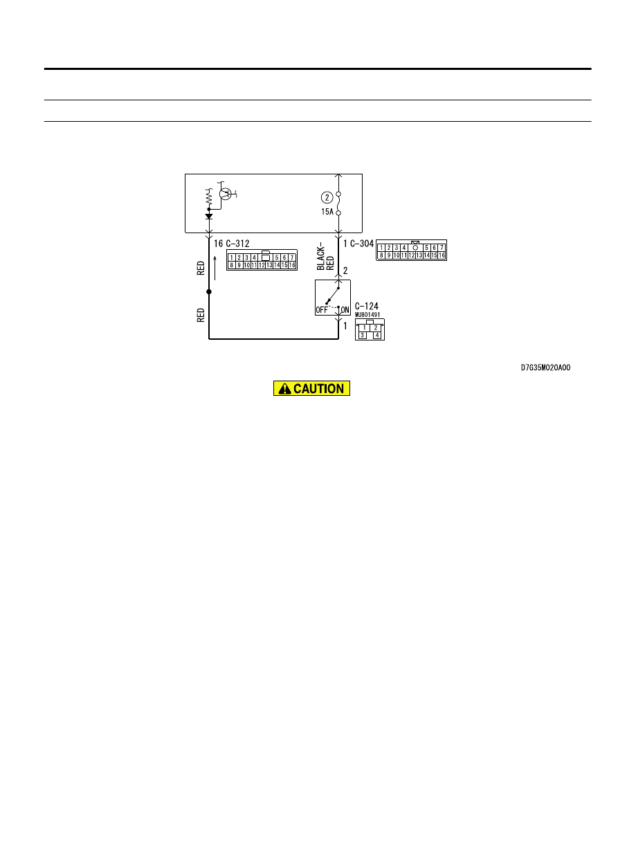
M13502000938USA0000010000

Stoplight Switch Circuit

ETACS-ECU

STOPLIGHT 
SWITCH

If there is any problem in the CAN bus lines, an incorrect
diagnostic trouble code may be set. Prior to this diagnosis,
diagnose the CAN bus lines. (Refer to GROUP 54D, Trouble
code diagnosis P.54D-17).

CIRCUIT OPERATION
ETACS-ECU sends the ON signal generated when the brake
pedal  is  depressed  and  OFF  signal  generated  when  it  is
released to ABS-ECU via the CAN bus lines.

DTC SET CONDITIONS
This diagnostic trouble code is set in the following case.

When the vehicle has run for a long time with the stop light
switch turned ON.

When there is difference between the stop light switch state
and the vehicle's behavior

PROBABLE CAUSES

Improper adjustment of stop light switch installation position

Malfunction of the stop light switch

Damaged wiring harness and connectors

Malfunction of ETACS-ECU

ABS-ECU malfunction

ANTI-LOCK BRAKING SYSTEM (ABS)

35B-95

ANTI-LOCK BRAKING SYSTEM (ABS) DIAGNOSIS

DIAGNOSIS

Required Special Tools:

MB991958: Scan Tool (M.U.T.-III Sub Assembly)

MB991824: Vehicle Communication Interface (V.C.I.)

MB991827: M.U.T.-III USB Cable

MB991910: M.U.T.-III Main Harness A

MB991974: ABS check harness

STEP 1. M.U.T.-III CAN bus diagnostics
Use scan tool to diagnose the CAN bus lines.

Q:Is the check result normal?

YES:

 Go to Step 3.

NO:

 Repair the CAN bus lines. (Refer to GROUP 54D - CAN

Bus Diagnostics table P.54D-17.) On completion, go to
Step 2.

STEP 2. Diagnostic trouble code recheck after resetting
CAN bus lines

Q:Is DTC C1000 set?

YES:

 Go to Step 3.

NO:

 The procedure is complete.

STEP 3. Stop light operation check

(1)

Turn the ignition switch to the ON position.

(2)

Check  the  stop  light  operation  when  the  brake  pedal  is
depressed.  Check  that  the  stop  light  illuminates  when  the
brake pedal is depressed and that it goes out when the brake
pedal is released.

OK:

When the brake pedal is released: OFF
When the brake pedal is depressed: ON

Q:Is the check result normal?

YES:

 Go to Step 9.

NO:

 Go to Step 4.

STEP 4. Check for stop light switch installation
Refer to GROUP 35A - On-vehicle Service P.35A-24.

Q:Is the check result normal?

YES:

 Go to Step 5.

NO:

 Install the stop light switch correctly.

STEP 5. Stop light switch continuity check

(1)

Remove the stop light switch. (Refer to GROUP 35A -Brake
Pedal P.35A-22.)

35B-96

ANTI-LOCK BRAKING SYSTEM (ABS)

ANTI-LOCK BRAKING SYSTEM (ABS) DIAGNOSIS

AC102416

ZC501246AA01

4 ± 0.5 mm  
(0.16 ± 0.02 in)

No continuity

Continuity

(2)

Connect the circuit tester (Ω range) to the stop light switch
connector terminals No. 1 and 2.

(3)

When no continuity is detected with the plunger pressed from
the edge of the outer case by the dimension shown in the
figure  and  when  continuity  is  detected  with  the  plunger
released, the stop light switch is in good condition.

Q:Is the check result normal?

YES:

 Go to Step 6.

NO:

 Replace the stop light switch.

STEP 6. Voltage measurement at C-304 ETACS-ECU
connector

(1)

Turn the ignition switch to the ON position.

ZC604534 0000

ETACS-ECU side: C-304

(2)

Measure the voltage between the terminal No. 1 and the body
ground.

OK: 12 volts (Battery voltage)

Q:Is the check result normal?

YES:

 Go to Step 8.

NO:

 Go to Step 7.

STEP 7. Connector check: C-304 ETACS-ECU connector,
C-124 stop light switch connector

Q:Is the check result normal?

YES:

 The short circuit between the C-304 ETACS-ECU

connector terminal No. 1 and the C-124 stop light switch
connector terminal No. 2 may be present. Repair the wiring
harness between the C-304 ETACS-ECU connector terminal
No. 1 and the C-124 stop light switch connector terminal
No. 2.

NO:

 Repair the defective connector.

STEP 8. ETACS-ECU fuse No.2 check

Q:Is the check result normal?

YES:

 Replace the ETACS-ECU, and then go to Step 11.

NO:

 Go to Step 9.

STEP 9. Voltage measurement at C-312 ETACS-ECU
connector

(1)

Turn the ignition switch to the ON position.

ANTI-LOCK BRAKING SYSTEM (ABS)

35B-97

ANTI-LOCK BRAKING SYSTEM (ABS) DIAGNOSIS

ZC604535

Harness side: C-312

0000

(2)

Measure the voltage between the terminal No. 16 and the
body ground.

OK: Approx. 5 volt

Q:Is the check result normal?

YES:

 Go to Step 10.

NO:

 Replace the ETACS-ECU, and then go to Step 11.

STEP 10. Connector check: C-312 ETACS-ECU connector,
C-124 stop light switch connector

Q:Is the check result normal?

YES:

 The short circuit between the C-312 ETACS-ECU

connector terminal No. 16 and the C-124 stop light switch
connector terminal No. 1 may be present. Repair the wiring
harness between the C-312 ETACS-ECU connector terminal
No. 16 and the C-124 stop light switch connector terminal
No. 1.

NO:

 Repair the defective connector.

STEP 11. Check whether the diagnostic trouble code is
reset.

Q:Is DTC 1000 set?

YES:

 Replace the ABS-ECU.

NO:

 The procedure is complete.

DTC C2200: Abnormality in ABS-ECU

M13502000939USA0000010000

If there is any problem in the CAN bus lines, an incorrect
diagnostic trouble code may be set. Prior to this diagnosis,
diagnose the CAN bus lines. (Refer to GROUP 54D, Trouble
code diagnosis P.54D-17
).

CIRCUIT OPERATION

ABS-ECU controls ABS by calculating the data sent from the
wheel speed sensor.

The ABS-ECU always monitors itself while the system is in
operation. If the ABS-ECU detects any faults, it will set this
DTC.

DTC SET CONDITIONS
This diagnostic trouble code is set when ABS-ECU or G sensor
(AWD) has malfunction.

PROBABLE CAUSES
ABS-ECU malfunction

35B-98

ANTI-LOCK BRAKING SYSTEM (ABS)

ANTI-LOCK BRAKING SYSTEM (ABS) DIAGNOSIS


Content   ..  631  632  633  634   ..