Mitsubishi Outlander XL. Manual - part 580


  Index      Mitsubishi     Mitsubishi Outlander XL - service repair manual 2007 year


Search            


Content   ..  578  579  580  581   ..


Mitsubishi Outlander XL. Manual - part 580


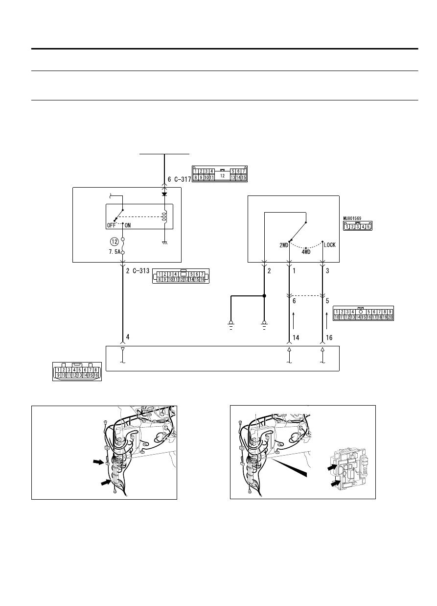
Inspection Procedure 2: The Switch Position of the Drive Mode Selector does not Match
with the Indicator Display in the Combination Meter.

M12704100032USA0000010000

ETACS-
ECU

IGNITION
SWITCH (IG1)

IG1
RELAY

AWD-ECU

DRIVE MODE
SELECTOR

D7G27M001A00

GREY

WHITE

BLA

CK

BLA

CK

BLA

CK

VIOLET

VIOLET

LIGHT

GREEN

LIGHT

GREEN

C-128

C-32

C-23

ZC6000240001

Connectors: C-32, C-128

C-128

C-32

ZC6000260001

ETACS-ECU
(front view)

C-313
(BR)

C-317

Connectors: C-313, C-317

ELECTRONIC CONTROL AWD

27C-79

DIAGNOSIS

ZC6000350000

C-23

Connector: C-23


DRIVE MODE SELECTOR POSITION AND INDICATOR
DISPLAY (NORMAL)

ZC6000190000

Drive mode indicator

Vehicles for USA

ZC6000200000

Drive mode indicator

Vehicles for Canada

ZC6000130000

Drive mode
selector

Switch position

Indicator display

FWD (2WD)

-(Not illuminated)

AWD (4WD)

AWD

LOCK

AWD, LOCK


27C-80

ELECTRONIC CONTROL AWD

DIAGNOSIS

COMMENTS ON TROUBLE SYMPTOM

If the drive mode selector switch position and indicator display
in  the  combination  meter  do  not  match,  the  drive  mode
selector, wiring harness connector between AWD-ECU and
drive  mode  selector,  wiring  harness  connector  in  the  earth
circuit for the drive mode selector, or AWD-ECU may have a
problem.

If high-pressure type spare tires are equipped, tire pressure is
excessively out of the specified value, or tires with different
sizes or different brands are equipped, AWD mode may be
temporarily displayed even when the LOCK mode is selected.

TROUBLESHOOTING HINTS

Damaged wiring harness and connectors

Malfunction of drive mode selector

AWD-ECU malfunction

High-pressure  type  spare  tires  are  equipped,  tire
pressure is excessively out of the specified value,
or tires with different sizes or different brands are
equipped

DIAGNOSIS

MB991958: Scan Tool (M.U.T.-III Sub Assembly)

MB991824: Vehicle Communication Interface

MB991827: M.U.T.-III USB Cable

MB991910: M.U.T.-III Main Harness A

NOTE: 

Be sure to ask the user if any of the probable causes

is applicable before performing the diagnosis procedure.
STEP 1. Check the following connector:
Check the C-23 drive mode selector connector and C-128 AWD-
ECU connector for improper engagement, terminal damage or
terminal drawn in the connector case.

Q:Are the connectors and terminals in good condition?

YES:

 Go to Step 2.

NO:

 Repair the connector(s) or terminal(s). Then go to

Step 9.

STEP 2. Resistance measurement between the drive mode
selector connector terminals

ZC3052090001

(1)

Remove the drive mode selector (Refer P.27C-93.)

ELECTRONIC CONTROL AWD

27C-81

DIAGNOSIS

ZC3047570000

C-23 drive mode 
selector connector: 
component side 

(2)

Measure the resistance between the following terminals.

Switch position

Terminal
number

Normal
conditions

FWD

1 - 2

Continuity
exists (2 ohm
or less).

AWD

-

No continuity

LOCK

2 - 3

Continuity
exists (2 ohm
or less).

Q:Is the check result normal?

YES:

 Go to Step 3.

NO:

 Replace the drive mode selector. Then go to Step 9.

STEP 3. Wiring harness check

Wiring  harness  between  the  C-128  AWD-ECU  connector
(terminal No. 16) and the C-23 drive mode selector connector
(terminal No. 3)

Wiring  harness  between  the  C-128  AWD-ECU  connector
(terminal No. 14) and the C-23 drive mode selector connector
(terminal No. 1)

Check the wiring harness above for damage or other problem.

Q:Is the wiring harness in good condition?

YES:

 Go to Step 4.

NO:

 Repair the wiring harness. Then go to Step 9.

STEP 4. Resistance measurement at the drive mode
selector connector

(1)

Disconnect the C-23 drive mode selector connector.

ZC3047230000

C-23 harness 
connector: 
harness side 

(2)

Measure  the  resistance  between  the  C-23  wiring  harness
side connector terminal No. 4 and the body earth.

OK: 2 ohm or less

Q:Is the check result normal?

YES:

 Go to Step 8.

NO:

 Go to Step 5.

STEP 5. Wiring harness check

NOTE: 

Prior to the wiring harness inspection, check the

C-32 joint connector, and repair if necessary.

27C-82

ELECTRONIC CONTROL AWD

DIAGNOSIS


Content   ..  578  579  580  581   ..