Mitsubishi Outlander XL. Manual - part 575
ZC6000240002
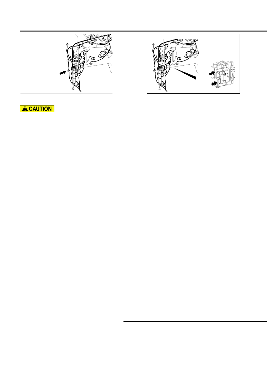
Connectors: C-128
C-128
ZC6000260001
ETACS-ECU
(front view)
C-313
(BR)
C-317
Connectors: C-313, C-317
⦆
If more than three minutes elapse after the
ignition switch is turned ON without starting
engine, AWD-ECU may set DTC U0100 as past
trouble.
⦆
If there is any problem in the CAN bus lines, an
incorrect DTC may be set. Prior to this
diagnosis, always diagnose the CAN bus lines.
⦆
Before replacing the ECU, ensure that the
communication circuit is normal.
OPERATION
AWD-ECU temporarily limits the AWD functions if it
has not received the signal from the engine-ECU.
DTC SET CONDITIONS
If the following conditions are met when the system is
in operation (always), AWD-ECU gradually switches
the control from AWD to AWD AUTO, flashes the
AWD/LOCK indicators alternately, and sets the DTC
No. U0001.
⦆
IG1 power supply voltage: 10 V or more
⦆
Chassis No. signal, throttle angle signal, or engine
speed signal cannot be received.
TROUBLESHOOTING HINTS
Current trouble
⦆
Wiring harness or connector failure in the CAN bus
lines between the engine ECU and AWD-ECU
⦆
Engine ECU malfunction
⦆
AWD-ECU malfunction
Past trouble
⦆
Refer to "How to treat past trouble" (GROUP 00 -
How to Treat Past Trouble P.00-17) for proceeding
the diagnostics. Diagnose mainly wiring harness or
connector failure in the CAN bus lines between the
engine ECU and AWD-ECU, and malfunction in the
power supply system for the engine ECU.
NOTE:
For a past trouble, you cannot find it by
the scan tool MB991958 CAN bus diagnostics even
if there is any failure in CAN bus lines. In
this case, check the CAN bus lines in the same
manner as How to cope with intermittent
malfunction (refer to GROUP 00 - How to Cope
with Intermittent Malfunction P.00-15). You can
narrow down the possible cause of the trouble by
referring to the DTC, which is set regarding the
CAN communication-linked ECUs. (Refer to GROUP
54D - CAN Bus Line Diagnostic Flow P.54D-10.)
DIAGNOSIS
⦆
MB991958: Scan Tool (M.U.T.-III Sub Assembly)
⦆
MB991824: Vehicle Communication Interface
⦆
MB991827: M.U.T.-III USB Cable
⦆
MB991910: M.U.T.-III Main Harness A
STEP 1. Scan tool MB991958 CAN bus diagnostics
Use scan tool MB991958 to diagnose the CAN bus lines.
Q:Is the check result normal?
ELECTRONIC CONTROL AWD
27C-59
DIAGNOSIS