Mitsubishi Outlander XL. Manual - part 572
STEP 4. Wiring harness check
Check the wiring harness between the C-128 AWD-ECU
connector and the C-315 ETACS-ECU connector for damage or
other problem.
Q:Is the wiring harness in good condition?
YES:
Go to Step 5.
NO:
Repair damage or other problem in the wiring harness.
Then go to Step 8.
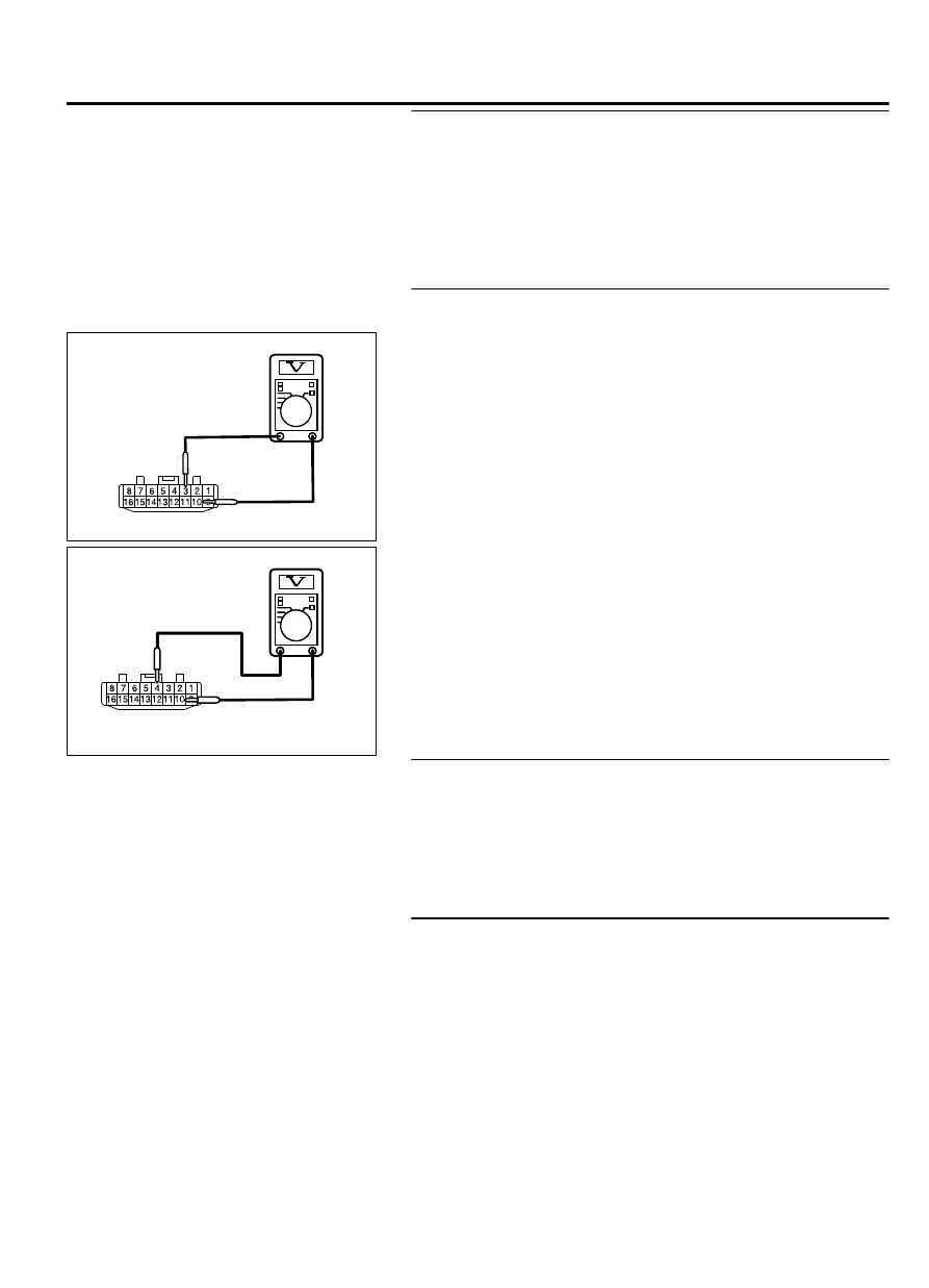
STEP 5. Voltage measurement at the AWD-ECU connector
(1)
Disconnect the C-128 AWD-ECU connector.
C-128 harness
connector:
harness side
ZC3047190000
C-128 harness
connector:
harness side
ZC3047200000
(2)
Measure the voltage between the C-128 wiring harness side
connector terminals No. 3/4 and No. 10.
OK: Battery voltage
Q:Is the check result normal?
YES:
Go to Step 8.
NO:
Go to Step 6.
STEP 6. Wiring harness check
Check the wiring harness between the C-128 AWD-ECU
connector (terminal No. 3) and the C-309 ETACS-ECU
connector (terminal No. 1) for damage or other problem.
Q:Is the wiring harness in good condition?
YES:
Go to Step 7.
NO:
Repair the wiring harness. Then go to Step 8.
STEP 7. Check whether the DTC is reset.
(1)
Erase the DTC.
(2)
Turn the ignition switch from the LOCK (OFF) position to the
ON position.
(3)
Check if the DTC is set.
Q:Is the DTC No. C211E set?
YES:
Replace AWD-ECU. (Refer to P.27C-92.) Then go to
Step 8.
NO:
The trouble can be an intermittent malfunction.
(Refer to GROUP 00 - How to Cope with Intermittent
Malfunction P.00-15.)
ELECTRONIC CONTROL AWD
27C-47
DIAGNOSIS