Mitsubishi Outlander XL. Manual - part 543


  Index      Mitsubishi     Mitsubishi Outlander XL - service repair manual 2007 year


Search            


Content   ..  541  542  543  544   ..


Mitsubishi Outlander XL. Manual - part 543


REMOVAL SERVICE POINTS

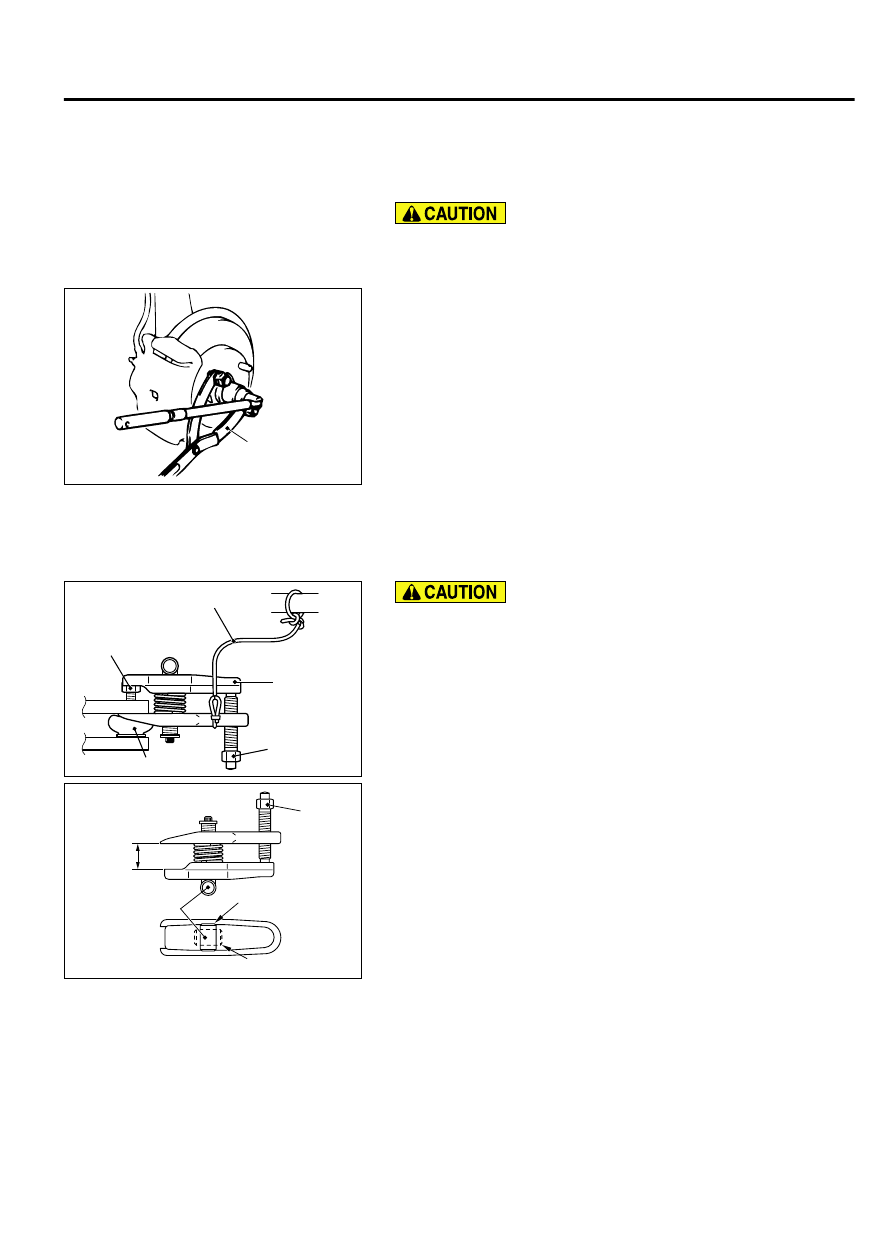
<<A>> DRIVESHAFT NUT REMOVAL

Do not apply the vehicle weight on the wheel bearing with
the driveshaft nut loosened. Otherwise, the wheel bearing
may be broken.

ZC5000630000

MB990767

Use special tool MB990767 to counter the hub as shown in the
figure to remove the driveshaft nut.


<<B>> SELF-LOCKING NUT (TIE-ROD END CONNECTION)
REMOVAL

ZC5018680000

Cord

Bolt

MB991897
or
MB992011

Nut

Ball joint

Loosen the self-locking nut (tie-rod end connection) from
the ball joint, but do not remove here. Use the special tool.

To prevent the special tool from dropping off, suspend it
with a rope.

1.

Install special tool MB991897 or MB992011, as shown in the
figure.

ZC5000600000

Parallel

Knob

Bolt

Correct

Wrong

2.

Turn the bolt and knob to make the special tool jaws parallel,
then hand-tighten the bolt. After tightening, check that the jaws
are still parallel.

NOTE: 

To adjust the special tool jaws to be parallel, set

the orientation of the knob as shown in the figure.

3.

Unscrew the bolt to disconnect the ball joint.


FRONT AXLE

26-19

DRIVESHAFT ASSEMBLY

<<C>> DRIVESHAFT ASSEMBLY REMOVAL

ZC5018620000

Oil seal

Magnetic
encoder

Wheel
bearing

ZC5018880000

MB990767

MB990242 MB991354

MB990244
(Three)

The magnetic encoder collects metallic particles easily,
because  it  is  magnetized.  Make  sure  that  the  magnetic
encoder does not collect metallic particles.

When removing the driveshaft, make sure that it does not
contact  with  the  magnetic  encoder  (integrated  with  the
inner oil seal) to avoid damage.

1.

If  the  driveshaft  is  seized  with  the  hub,  use  special  tools
MB990242  and  MB990244,  MB990767  and  MB991354  to
push the driveshaft assembly out from the hub.

ZC501890AA00

Driveshaft

2.

While  pulling  the  lower  side  of  the  brake  disc  toward  you,
remove the driveshaft assembly from the hub.

Never  pull  out  the  driveshaft  assembly  from  the  EBJ
assembly  side.  Otherwise,  the  PTJ  assembly  may  be
damaged. Always pull out from the PTJ side with a lever.

Care  must  be  taken  to  ensure  that  the  oil  seal  of  the
transaxle  is  not  damaged  by  the  spline  part  of  the
driveshaft assembly.

ZC501891AA00

PTJ assembly

Transmission

Lever

3.

Insert  a  lever  between  the  transaxle  case  or  transfer  and
driveshaft assembly, and then pull the driveshaft assembly out
from the transaxle.

26-20

FRONT AXLE

DRIVESHAFT ASSEMBLY

AC210315

ZC5018840001

MB991017

MB991000

Do not apply the vehicle weight to the wheel bearing with
the driveshaft assembly removed. If, however, the vehicle
weight shall be applied to the bearing (in order to move the
vehicle), tighten the following special tools MB991000 and
MB991017 to the specified torque 160 ± 16 N·m (118 ± 11 ft-
lb).

INSTALLATION SERVICE POINTS

>>A<< DRIVESHAFT ASSEMBLY INSTALLATION

ZC5018620000

Oil seal

Magnetic
encoder

Wheel
bearing

The magnetic encoder collects metallic particles easily,
because  it  is  magnetized.  Make  sure  that  the  magnetic
encoder should not collect metallic particles. Check that
there is not any trouble prior to reassembling it.

When installing the driveshaft, make sure that it does not
contact  with  the  magnetic  encoder  (integrated  with  the
inner oil seal) to avoid damage.

Care  must  be  taken  to  ensure  that  the  oil  seal  of  the
transaxle  is  not  damaged  by  the  spline  part  of  the
driveshaft assembly.


>>B<< WASHER/DRIVESHAFT NUT INSTALLATION

Do  not  apply  the  vehicle  weight  on  the  front  wheel  hub
assembly  before  fully  tightening  the  driveshaft  nut.
Otherwise, the wheel bearing may be broken.

ZC5018640000

Washer

MB990767

1.

Incorporate the driveshaft assembly washer as shown in the
illustration.

2.

Use special tool MB990767 to tighten the driveshaft nuts. At
this  time,  tighten  the  nuts  within  the  specified  torque  range
considering the final tightening.

Tightening torque: 144 - 176 N·m (107 - 129 ft-lb)

3.

If the pin holes do not align with the pins, tighten the driveshaft
nut [less than 200 N·m(147 ft-lb)] and find the nearest hole
then bend the cotter pin to fit it.

FRONT AXLE

26-21

DRIVESHAFT ASSEMBLY

DISASSEMBLY AND ASSEMBLY <FWD>

M12601000037USA0000010000

As for the EBJ assembly, only the EBJ boot can
be  replaceable,  and  other  parts  cannot  be
disassembled.

ZC5018950000

17

15

14

5

13

9

12

11

10

8

13

5

7

6

7

3

10

11

9

13

10

11

12

9

13

13

14

17

1

2

13

5

14

15

17

1

2

13

14

1

2

20

19

2

N

1

N

N

N

N

<RH>

<LH>

18

20

21

19

21

N

Grease
for PTJ

Grease
for EBJ

EBJ boot repair kit

PTJ boot repair kit

PTJ repair kit

Bracket assembly repair kit

Bearing dust seal repair kit

4

4

4

16

16

16

16

Disassembly steps

>>F<<

1.

PTJ boot band (large)

>>F<<

2.

PTJ boot band (small)

>>E<<

3.

PTJ case and inner shaft assembly RH

<<A>>

>>E<<

4.

Seal plate

Disassembly steps

<<B>>

5.

PTJ case

<<C>>

>>D<<

6.

Inner shaft RH

7.

Dust cover RH

8.

Bracket assembly RH

26-22

FRONT AXLE

DRIVESHAFT ASSEMBLY


Content   ..  541  542  543  544   ..