Mitsubishi Outlander XL. Manual - part 541


  Index      Mitsubishi     Mitsubishi Outlander XL - service repair manual 2007 year


Search            


Content   ..  539  540  541  542   ..


Mitsubishi Outlander XL. Manual - part 541


REMOVAL SERVICE POINTS

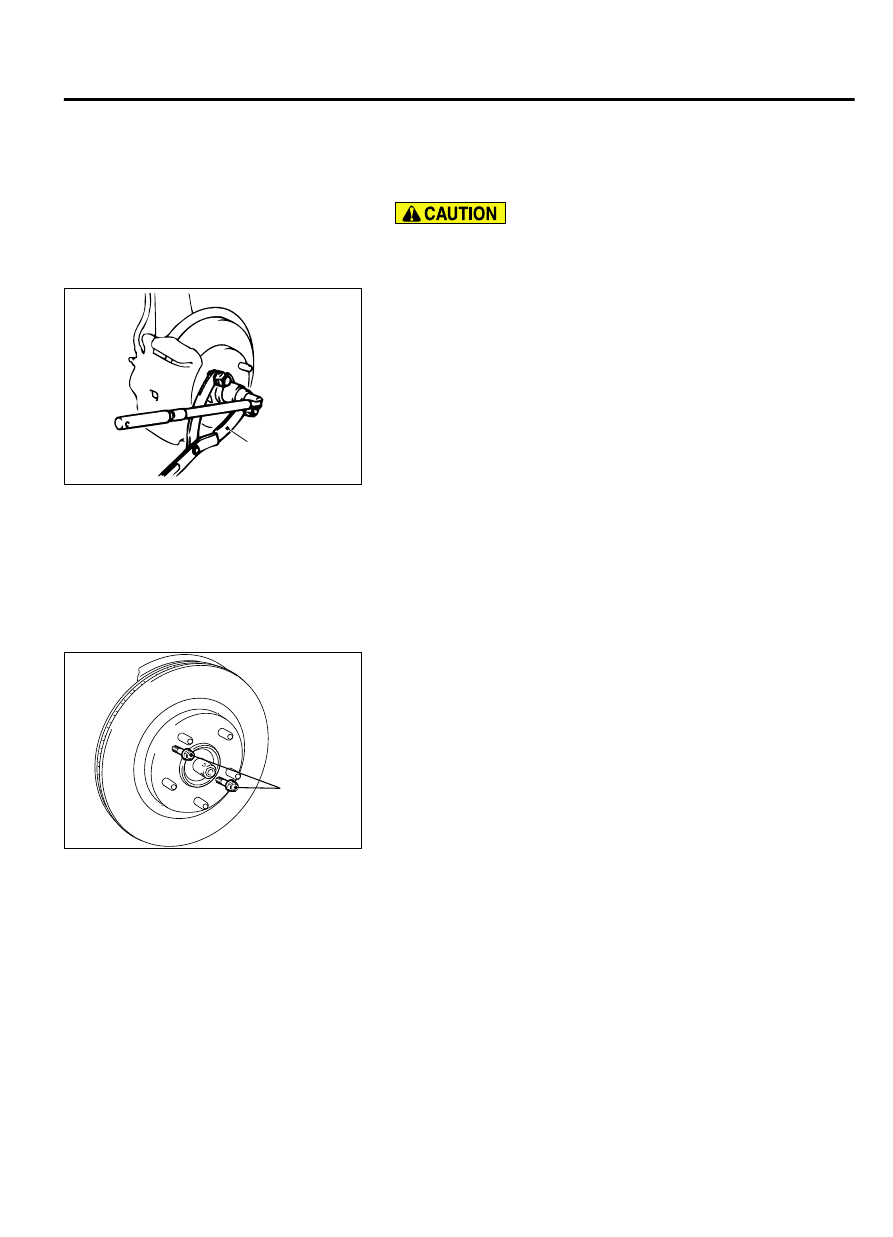
<<A>> DRIVESHAFT NUT REMOVAL

Do  not  apply  the  vehicle  weight  on  the  front  wheel  hub
assembly with the driveshaft nut loosened. Otherwise, the
wheel bearing may be broken.

ZC5000630000

MB990767

Use special tool MB990767 to counter the hub as shown in the
figure to remove the driveshaft nut.


<<B>> CALIPER ASSEMBLY REMOVAL
Secure the removed caliper assembly with wire, etc.


<<C>> BRAKE DISC REMOVAL

ZC5018610000

Bolts
(M8 × 1.25)

If the brake disc removal is difficult, install bolts (M8 x 1.25 mm)
shown in the figure, and tighten them evenly and gradually to
remove the brake disc.


FRONT AXLE

26-11

FRONT AXLE HUB ASSEMBLY

<<D>> SELF-LOCKING NUT (TIE-ROD END CONNECTION)
REMOVAL

ZC5018680000

Cord

Bolt

MB991897
or
MB992011

Nut

Ball joint

Loosen the self-locking nut (tie-rod end connection) from
the ball joint, but do not remove here. Use the special tool.

To prevent the special tool from dropping off, suspend it
with a rope.

1.

Install special tool MB991897 or MB992011 as shown in the
figure.

ZC5000600000

Parallel

Knob

Bolt

Correct

Wrong

2.

Turn the bolt and knob to make the special tool jaws parallel,
then hand-tighten the bolt. After tightening, check that the jaws
are still parallel.

NOTE: 

To adjust the special tool jaws to be parallel, set

the orientation of the knob as shown in the figure.

3.

Unscrew the bolt to disconnect the ball joint.

<<E>> DRIVESHAFT REMOVAL

ZC5018620000

Oil seal

Magnetic
encoder

Wheel
bearing

The magnetic encoder collects metallic particles easily,
because  it  is  magnetized.  Make  sure  that  the  magnetic
encoder does not collect metallic particles.

When removing the driveshaft, make sure that it does not
contact  with  the  magnetic  encoder  (integrated  with  the
inner oil seal) to avoid damage.

ZC5018630000

MB990767

MB990242

MB991354

MB990244
(Three)

If  the  driveshaft  is  seized,  use  special  tools  MB990242  and
MB990244, MB991354 and MB990767 to push the driveshaft
out from the hub.

26-12

FRONT AXLE

FRONT AXLE HUB ASSEMBLY

INSTALLATION SERVICE POINTS

>>A<< WASHER/DRIVESHAFT NUT INSTALLATION

ZC5018620000

Oil seal

Magnetic
encoder

Wheel
bearing

The magnetic encoder collects metallic particles easily,
because  it  is  magnetized.  Make  sure  that  the  magnetic
encoder should not collect metallic particles. Check that
there is not any trouble prior to reassembling it.

When installing the driveshaft, make sure that it does not
contact  with  the  magnetic  encoder  (integrated  with  the
inner oil seal) to avoid damage.

Do  not  apply  the  vehicle  weight  on  the  wheel  bearing
before fully tightening the driveshaft nut. Otherwise, the
wheel bearing may be broken.

ZC5018640000

Washer

MB990767

1.

Be  sure  to  install  the  driveshaft  washer  in  the  illustrated
direction.

2.

Use special tool MB990767 to tighten the driveshaft nuts. At
this  time,  tighten  the  nuts  within  the  specified  torque  range
considering the final tightening.

Tightening torque: 144 - 176 N·m (107 - 129 ft-lb)

3.

If the pin holes do not align with the pins, tighten the driveshaft
nut [less than 200 N·m(147 ft-lb)] and find the nearest hole
then bend the cotter pin to fit it.

INSPECTION

M12601000018USA0000010000

Check the hub for cracks and spline for wear.

Check the knuckle for cracks.

Check for defective bearing.

NOTE: 

If the meshing of the wheel bearing outer race and

the knuckle, or of the wheel bearing inner race and the
hub, is loose, replace the bearing or damaged parts.

DISASSEMBLY AND ASSEMBLY

M12601000019USA0000010000

FRONT AXLE

26-13

FRONT AXLE HUB ASSEMBLY

ZC5018780000

N

N

4

1

5

3

2

Disassembly steps

1.

Snap ring

<<A>>

2.

Hub

3.

Dust cover

<<B>>

4.

Wheel bearing

5.

Knuckle
Assembly steps

5.

Knuckle

Assembly steps

>>A<<

4.

Wheel bearing

1.

Snap ring

>>B<<

2.

Dust cover

3.

Hub

>>C<<

·

Hub starting torque check

>>D<<

·

Wheel bearing end play check

Required Special Tools:

MB990326: Preload Socket

MB990810: Side Bearing Puller

MB990883: Rear Suspension Bushing Arbor

MB990890: Rear Suspension Bushing Base

MB990935: Installer Adapter

MB990938: Brass Bar

MB991000: Spacer

MB991017: Front Hub Remover and Installer

MB991056 or MB991355: Knuckle Arm Bridge

MB991388: Bush Remover Base

MB991576: Base


DISASSEMBLY SERVICE POINT

<<A>> HUB REMOVAL

In  the  hub  removal  operation,  make  sure  to  replace  the
wheel bearing with new one.

ZC5018790000

Tighten the nut
with the bolt 
secured

MB991056 or
MB991355

MB991017

MB991000

Use  special  tools  MB991017,  MB991056  or  MB991355,
MB991000 to pull out the hub from the knuckle.

26-14

FRONT AXLE

FRONT AXLE HUB ASSEMBLY


Content   ..  539  540  541  542   ..