Mitsubishi Outlander XL. Manual - part 500
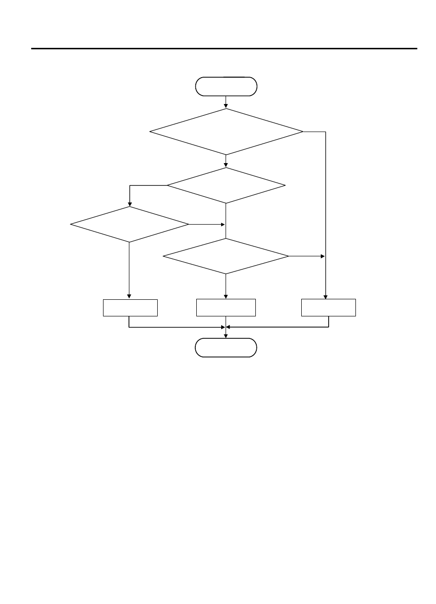
LOGIC FLOW CHARTS (Monitor Sequence)
ZC604085
Continuous failure
for 200 msecs.
Good
Malfunction
END
START
No
No
Good
No
Yes
Yes
Yes
No
Yes
Short to ground
Open judgement
Ignition switch :ON
(Battery positive voltage
≧
2V)
0000
DTC SET CONDITIONS
Check Conditions <Circuit continuity ground>
⦆
Voltage of battery: 2 volts or more.
Judgement Criteria <Circuit continuity ground>
⦆
Ground short judgement: abnormal. (0.2 second)
Check Conditions <Circuit continuity open>
⦆
Voltage of battery: 2 volts or more.
⦆
Ground short judgement: normal.
Judgement Criteria <Circuit continuity open>
⦆
Open judgement: abnormal. (0.2 second)
OBD-II DRIVE CYCLE PATTERN
Start the engine, and keep the vehicle stopped in "P"
range for 5 seconds.
TROUBLESHOOTING HINTS (THE MOST LIKELY
CAUSES FOR THIS CODE TO BE SET ARE:)
⦆
Malfunction of the low-reverse brake shift solenoid
valve system circuit
⦆
Damaged harness or connector
⦆
Malfunction of the TCM
⦆
Malfunction of the low-reverse brake shift solenoid
valve (valve body assembly)
AUTOMATIC TRANSAXLE MECHANICAL
23A-115
AUTOMATIC TRANSAXLE DIAGNOSIS