Mitsubishi Outlander XL. Manual - part 456


  Index      Mitsubishi     Mitsubishi Outlander XL - service repair manual 2007 year


Search            


Content   ..  454  455  456  457   ..


Mitsubishi Outlander XL. Manual - part 456


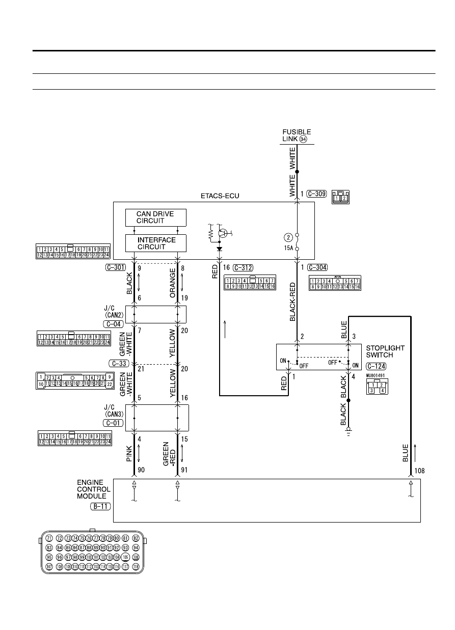
DTC 22: Stoplight Switch System

M11702000038USA0000010000

ZC6020490000

Stoplight Switch System Circuit

AUTO-CRUISE CONTROL SYSTEM

17b-17

AUTO-CRUISE CONTROL SYSTEM DIAGNOSIS


ZC6018500000

B-11 (GR)

Connector: B-11

ZC602050

C-04

C-01

C-33

Connectors: C-01, C-04, C-33, C-124

C-124

0000


ZC6020510000

C-309 (B)

C-301

C-304

Connectors: C-301, C-304, C-309, C-312

ETACS-ECU

C-312


CIRCUIT OPERATION
When  the  brake  pedal  is  depressed,  the  battery
positive voltage is applied to the ECM (terminal 108),
and the signal is transmitted from the ETACS-ECU to
the ECM via CAN bus line.

DTC SET CONDITIONS

Check Condition

The "CRUISE" indicator light illuminates.

Judgement Criteria

Short or open in stop light switch circuit.

Open  circuit  in  the  brake  switch  circuit  (between
ECM terminal 108 and ground).

Malfunction of CAN bus line.

TROUBLESHOOTING HINTS (The most likely
causes for this case:)

Malfunction of the stoplight switch.

Damaged harness or connector.

Malfunction of the ETACS-ECU

Malfunction of the ECM

DIAGNOSIS

Required Special Tools:

MB991958: Scan Tool (M.U.T.-III Sub Assembly)

MB991824: V.C.I.

MB991827: M.U.T.-III USB Cable

MB991910: M.U.T.-III Main Harness A

MB991223: Harness Set

MB992006: Extra Fine Probe

17b-18

AUTO-CRUISE CONTROL SYSTEM

AUTO-CRUISE CONTROL SYSTEM DIAGNOSIS

STEP 1. Using scan tool MB991958, diagnose the CAN bus
line.

ZC501967

AC404789

ZC5019680000

MB991824

MB991827

MB991910

Data link

connector

To prevent damage to scan tool MB991958, always turn the
ignition  switch  to  the  "LOCK"  (OFF)  position  before
connecting or disconnecting scan tool MB991958.

(1)

Connect  scan  tool  MB991958  to  the  data  link  connector
(Refer to P.17b-5).

(2)

Turn the ignition switch to the "ON" position.

(3)

Diagnose the CAN bus line (Refer to P.17b-5).

(4)

Turn the ignition switch to the "LOCK" (OFF) position.

(5)

Disconnect scan tool MB991958.

Q:Is the check result satisfactory?

YES:

 Go to Step 2

NO:

 Repair the CAN bus lines (Refer to GROUP 54D,

Diagnosis - CAN Bus Diagnostics Chart P.54D-17). Then
go to Step 15.

STEP 2. Using scan tool MB991958, check the data list item
74: Brake light switch.

(1)

Connect  scan  tool  MB991958  to  the  data  link  connector
(Refer to P.17b-5).

(2)

Turn the ignition switch to the "ON" position.

(3)

Set scan tool MB991958 to data reading mode for auto-cruise
control system (Refer to P.17b-5).

Item 74, Brake light switch.

When  the  brake  pedal  is  depressed,  the  display  on
scan tool MB991958 should be "ON".

When the brake pedal is released, the display on scan
tool MB991958 should be "OFF".

(4)

Turn the ignition switch to the "LOCK" (OFF) position.

(5)

Disconnect scan tool MB991958.

Q:Is the switch operating properly?

YES:

 Go to Step 9.

NO:

 Go to Step 3.

STEP 3. Using scan tool MB991958, check the ETACS
system data list item 290: Brake light switch.

(1)

Connect  scan  tool  MB991958  to  the  data  link  connector
(Refer to P.17b-5).

(2)

Turn the ignition switch to the "ON" position.

(3)

Set scan tool MB991958 to data reading mode for ETACS
system  (Refer  to  GROUP  54Ad,  Diagnosis  -  Data  List
Reference Table P.54Ad-51).

Item 290, Brake light switch.

When  the  brake  pedal  is  depressed,  the  display  on
scan tool MB991958 should be "ON".

AUTO-CRUISE CONTROL SYSTEM

17b-19

AUTO-CRUISE CONTROL SYSTEM DIAGNOSIS

When the brake pedal is released, the display on scan
tool MB991958 should be "OFF".

(4)

Turn the ignition switch to the "LOCK" (OFF) position.

(5)

Disconnect scan tool MB991958.

Q:Is the switch operating properly?

YES:

 Replace the ECM. When the ECM is replaced, register

the encrypted code (Refer to GROUP 42C, Diagnosis - ID
Code Registration Necessity Judgment Table P.42C-8).
Then go to Step 15.

NO:

 Go to Step 4.

STEP 4. Check fuse number 2 at the ETACS-ECU.

ZC6020520000

ETACS-ECU

Fuse number 2
(Housing color: Blue)

Q:Is the fuse in good condition?

YES:

 Go to Step 5.

NO:

 Check the stoplight system harness and replace the

fuse. Then go to Step 15.

STEP 5. Check the stoplight switch.

(1)

Remove the stoplight switch (Refer to GROUP 35A, Brake
Pedal P.35A-22).

ZC6020530000

C-124 Stoplight switch
connector

ZC602054

Continuity

No continuity

4.0 mm (0.16 in)

0000

Stop light switch

(2)

Connect  an  ohmmeter  to  the  stoplight  switch  between
terminals 1 and 2.

(3)

Check for continuity between the terminals when the plunger
of the stoplight switch is pushed in and when it is released.

(4)

The stoplight switch is operating properly if the circuit is open
between terminals 1 and 2 when the plunger is pushed in to
a depth of within 4.0 mm (0.16 inch) from the outer case edge
surface,  and  if  the  resistance  value  is  less  than  2  ohms
between terminals 1 and 2 when it is released.

Q:Is the stoplight switch operating properly?

YES:

 Install the stoplight switch (Refer to GROUP 35A,

Brake Pedal P.35A-22). Then go to Step 6.

NO:

 Replace the stoplight switch (Refer to GROUP 35A,

Brake Pedal P.35A-22). Then go to Step 15.

STEP 6. Check stoplight switch connector C-124 and
ETACS-ECU connector C-304 and C-312 for loose, corroded
or damaged terminals, or terminals pushed back in the
connector.

Q:Are the connectors and terminals in good condition?

17b-20

AUTO-CRUISE CONTROL SYSTEM

AUTO-CRUISE CONTROL SYSTEM DIAGNOSIS


Content   ..  454  455  456  457   ..