Mitsubishi Outlander XL. Manual - part 410


  Index      Mitsubishi     Mitsubishi Outlander XL - service repair manual 2007 year


Search            


Content   ..  408  409  410  411   ..


Mitsubishi Outlander XL. Manual - part 410


DIAGNOSIS

Required Special Tools:

MB991958: Scan Tool (M.U.T.-III Sub Assembly)

MB991824: V.C.I.

MB991827: USB Cable

MB991910: Main Harness A

STEP 1. Check harness connector B-16 at engine oil
pressure switch and harness connector B-10 at ECM for
damage.

Q:Is the harness connector in good condition?

YES:

 Go to Step 2.

NO:

 Repair or replace it. Refer to GROUP 00E, Harness

Connector Inspection P.00E-2. Then go to Step 7.

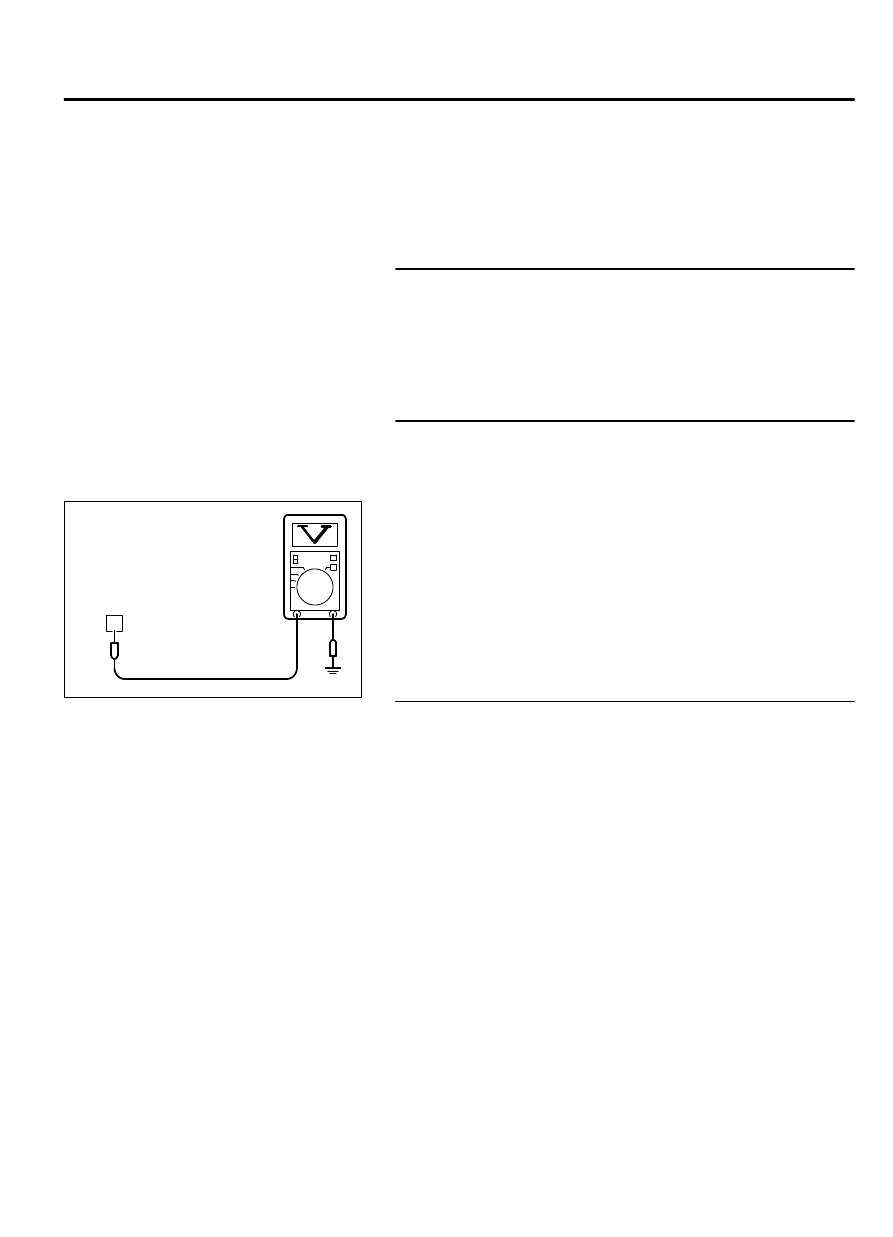
STEP 2. Measure the power supply voltage at engine oil
pressure switch connector B-16.

(1)

Disconnect the connector B-16 measure at the harness side.

(2)

Turn the ignition switch to the "ON" position.

1

ZK603873

B-16 harness 
connector: 
component side

AA00

(3)

Measure the voltage between terminal No. 1 and ground.

The voltage should equal battery positive voltage.

(4)

Turn the ignition switch to the "LOCK" (OFF) position.

Q:Is  battery  positive  voltage  (approximately  12  volts)

present?

YES:

 Go to Step 5.

NO:

 Go to Step 3.

STEP 3. Check for open circuit or short circuit to ground or
harness damage between engine oil pressure switch
connector B-16 and ECM connector B-10.

(1)

Disconnect  the  connector  B-16  and  B-10  measure  at  the
harness side.

MULTIPORT INJECTION SYSTEM (MFI) <DIAGNOSIS>

13Ab-835

SYMPTOM PROCEDURES

16

15 14 13 12 11 10 9 8 7 6 5 4

3

2

1

32

31 30 29 28 27 26 25 24 23 22 21 20 19 18

17

48

47 46 45 44 43 42 41 40 39 38 37 36 35 34

33

64

63 62 61 60 59 58 57 56 55 54 53 52 51 50

49

1

ZK603874AA00

B-16 harness connector: 
component side

B-10 harness connector: 
component side

(2)

Measure  the  resistance  between  connector  B-16  (terminal
No. 1) and connector B-10 (terminal No. 36).

Should be less than 2 ohms.

ZK603875

B-10 harness
connector: 
component side

AA00

16

15 14 13 12 11 10 9

8

7

6

5

4

3

2

1

32

31 30 29 28 27 26 25 24 23 22 21 20 19 18

17

48

47 46 45 44 43 42 41 40 39 38 37 36 35 34

33

64

63 62 61 60 59 58 57 56 55 54 53 52 51 50

49

(3)

Check for the continuity between connector B-10 (terminal
No. 36) and ground.

Not continuity.

Q:Is the harness wire in good condition?

YES:

 Then go to Step 4.

NO:

 Repair it. Then confirm that the malfunction symptom

is eliminated.

STEP 4. Measure the voltage at ECM connector B-10 by
using power plant ECU check harness special tool
MB992110.

ECM

ZK603234AA00

Body side harness 

MB992110

(1)

Disconnect  all  ECM  connectors.  Connect  the  power  plant
ECU  check  harness  special  tool  MB992110  between  the
separated connectors.

ZK603876

Special tool 64-pin 
connector:
component side 

AA00

16

15 14 13 12 11 10 9

8

7

6

5

4

3

2

1

32

31 30 29 28 27 26 25 24 23 22 21 20 19 18

17

48

47 46 45 44 43 42 41 40 39 38 37 36 35 34

33

64

63 62 61 60 59 58 57 56 55 54 53 52 51 50

49

(2)

Measure the voltage between terminal No. 36 and ground.
OK:
1 V or less (ignition switch: ON)
System voltage (during idling)

Q:

YES:

 It can be assumed that this malfunction is

intermittent.Refer to GROUP 00, How to Use
Troubleshooting/Inspection Service Points - How to Cope
with Intermittent Malfunctions P.00-15.

13Ab-836

MULTIPORT INJECTION SYSTEM (MFI) <DIAGNOSIS>

SYMPTOM PROCEDURES

NO:

 Replace the ECM. When the ECM is replaced, register

the ID code. Refer to GROUP 42B, ID Code Registration
Judgment Table <Vehicles with KOS> P.42B-12or GROUP
42C, ID Code Registration Judgment Table <Vehicles with
WCM> P.42C-8.

STEP 5. Measure the voltage at ECM connector B-10 by
using power plant ECU check harness special tool
MB992110.

ECM

ZK603234AA00

Body side harness 

MB992110

(1)

Disconnect  all  ECM  connectors.  Connect  the  power  plant
ECU  check  harness  special  tool  MB992110  between  the
separated connectors.

ZK603876

Special tool 64-pin 
connector:
component side 

AA00

16

15 14 13 12 11 10 9

8

7

6

5

4

3

2

1

32

31 30 29 28 27 26 25 24 23 22 21 20 19 18

17

48

47 46 45 44 43 42 41 40 39 38 37 36 35 34

33

64

63 62 61 60 59 58 57 56 55 54 53 52 51 50

49

(2)

Measure the voltage between terminal No. 36 and ground.
OK:
1 V or less (ignition switch: ON)
System voltage (during idling)

Q:

YES:

 It can be assumed that this malfunction is

intermittent.Refer to GROUP 00, How to Use
Troubleshooting/Inspection Service Points - How to Cope
with Intermittent Malfunctions P.00-15.

NO:

 Replace the engine oil pressure switch. Then confirm

that the malfunction symptom is eliminated.

DATA LIST REFERENCE TABLE

M11310100004USA0000010000

When shifting the selector lever to D range, the
brakes  should  be  applied  so  that  the  vehicle
does not move forward.

Driving  tests  always  need  two  persons:  one
driver and one observer.

NOTE: 

*1: In a new vehicle [driven approximately

500 km (311 mile) or less], the mass airflow
sensor output value is sometimes 10% higher than
the standard value.

NOTE: 

*2: The injector drive time represents the

time when the cranking speed is at 250 r/min or
below when the power supply voltage is 11 volts.

NOTE: 

*3: In a new vehicle [driven approximately

500 km (311 mile) or less], the injector drive

time is sometimes 10% longer than the standard
time.

NOTE: 

*4: Vehicles for Canada, the headlight,

taillight, etc. remain lit even when the lighting
switch is in "OFF" position but this is no problem
for checks.

MULTIPORT INJECTION SYSTEM (MFI) <DIAGNOSIS>

13Ab-837

DATA LIST REFERENCE TABLE

M.U.T.-III
SCAN
TOOL
DISPLAY

ITEM
NO.

INSPECTION
ITEM

INSPECTION
REQUIREMENT

NORMAL
CONDITION

INSPECTI
ON
PROCED
URE NO.

REFER
ENCE
PAGE

A/C
compress
or relay

93

A/C
compressor
relay

Engine: warming up, idling

A/C switch: "OFF"

OFF

Procedure
No. 25

 P.

13Ab
-831

Engine:
warming  up,
idling

A/C  switch:
"ON"

A/C
compressor
clutch  is  not
operating

OFF

A/C
compressor
clutch

 is

operating

ON

A/C SW1 76

A/C switch

Engine: warming up, idling

A/C switch: "OFF"

OFF

Procedure
No. 25

 P.

13Ab
-831

Engine:
warming  up,
idling

A/C  switch:
"ON"

A/C
compressor
clutch  is  not
operating

OFF

A/C
compressor
clutch

 is

operating

ON

Absolute
load
value

72

Absolute  load
value

Engine:
warming up

Engine idling

10 - 20%

-

-

2,500 r/min

10 - 20%

Revving
engine

Load

 value

increases
according  to
amount

 of

revving.

Airflow
sensor

10

Mass  airflow
sensor*1

Engine
coolant
temperature
:  80  -  95°C
(176  -  203°
F)

Lights,
electric
cooling  fan
and

 all

accessories:
"OFF"*4

Transaxele:
"P" range

Engine

 is

idling

1,350  -  1,670
mV

-

-

2,500 r/min

1,620  -  2,020
mV

Engine

 is

revved

Increase

 in

response

 to

revving

13Ab-838

MULTIPORT INJECTION SYSTEM (MFI) <DIAGNOSIS>

DATA LIST REFERENCE TABLE


Content   ..  408  409  410  411   ..